The TEAM
Igor Belyayev, Elli Rappaport, Nicholas Powel
Video Introduction: http://www.youtube.com/watch?v=lAjVIXVir5o
Lung Bioreactor
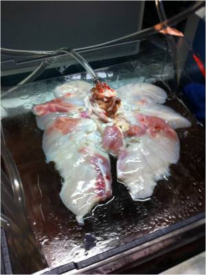
Lung transplants require an exact match between the donor and patient and even so are challenging and only rarely successful in the long run. In an effort to increase the success rate of lung transplants we are designing a lung bioreactor in order to facilitate the genetic remodeling of a lung. The bioreactor will imitate the conditions in the human body in order to keep the lung alive while utilizing stem cells to genetically remodel the lung in order to match the patient’s needs.
Problem Statement
- Lung disease kills approximately 400,000 people in the United States each year.1)
- Lung transplants are only 10-20% successful over the course of ten years.2)
We need to engineer an environment that will allow for the decellularization and subsequent repopulation of human lungs suitable for transplant.
- When the current process was used on rats it was noticed that the new cells did not fully grow on all parts of the lung which led to some small clots.3)
Schedule and Minutes
Background Research
In Harvard4), Yale5), and Columbia6) doctors have been working on a process using a Lung Bioreactor in order to more successfully perform lung transplants. This process involves using a special detergent to remove the current cells on the lung, leaving the lungs matrix or scaffolding, which is identical in every body. The now-white lung is placed in the bioreactor, which is designed to simulate the conditions (pressure, temperature, etc.) so that the new cells of the lung acceptor can properly grow on the lung scaffolding. Thus far these experiments have created working lungs, but only for a short period of time due to the cells not fully and properly regrowing in the bioreactor.7)
For a video of the process see: http://goo.gl/oTwCD
The video was taken from the Yale University School of Medicine and edited. The full video can be found athttp://www.eurekalert.org/multimedia/pub/23303.php?from=163046.
Links to Research Pages
Functions and Designs
Video: First System Test with New Chamber The quintessence of the bioreactor system is the lung chamber. The system employs two transparent chambers in which lung segments are sustained while completely surrounded by water. The lung segments are specially bagged and never directly contact the chamber water. By pumping water into and out of a chamber, we can cause lung segments to contract and expand without directly pumping the segments' tracheal fluid in and out. More closely mimicking the mechanics of the human body than other designs, we use the pressure surrounding the lung segment to control lung respiratory action.
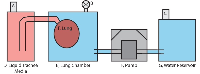
Figure 1 shows the basic setup of only the lung-pumping portion subsystem for one lung in one chamber. The system is prepared by first filling fitting the lung to the appropriate fitting and then filling the lung chamber, E with a full volume of water. The valve at B is set to open and a little more water is pumped in until it overflows through the valve. This is done to ensure that no air is present in the lung chamber. The valve at B is then closed.
For the lung compression stage, the water in reservoir G is pumped into the lung chamber. The water volume pumped into the chamber must displace the lung volume because this water has nowhere else to go, and so a net positive pressure results on the surface of the lung. This positive pressure forces the fluid in the lung out into D, the trachea fluid reservoir, contracting the lung.
When pumping stops, the lung maintains the volume it has at the end of pumping due to the fact that reservoirs D and G are open to the atmosphere via sterile air filters A and D. There is no pressure build up in any reservoir and so equilibrium between the lung and the water in the lung chamber is maintained.
For the lung expansion stage, the pump reverses direction and pumps water out of the lung chamber. Once again the volume of water lost from the lung chamber must be displaced by the lung because this is the only presence in the chamber that can make up the lost volume. Fluid from reservoir D is forced into the lung by this process and the lung expands.
Figure 1: Diagram of the Lung-Pumping Subsystem
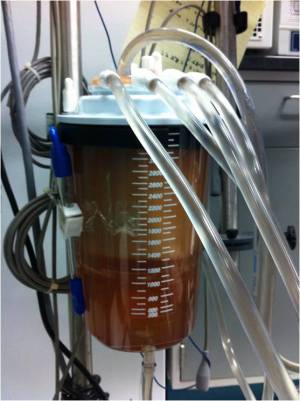
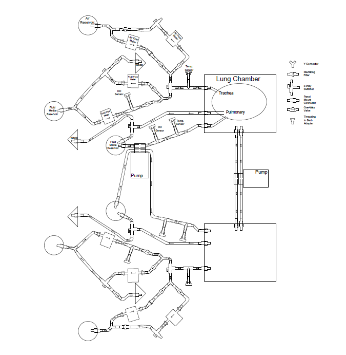
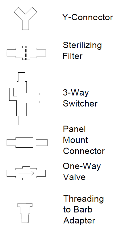
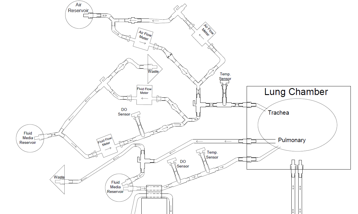
Two separate but interdependent media circuits operate in the system; one circuit supplies liquid media flow for segments' pulmonary system, and the other supplies liquid media for the tracheal system. Below are fluid flow circuit diagrams for the two media circuits as well as the negative pressure system (they have since been updated). In addition, we have attached pictures of some of the components of our prototype. Beneath those is a link to our past designs and plans.
Pictures of Some of Our Subsystems
System Physics
Function tree for a rigid lung chamber design 2011 Lung Bioreactor Rigid Prototype
Materials
Chamber
We need a lung chamber that can fully withstand the pressures that result from inflating and compressing the lung. Our original efforts involved using a variety of standard containers from the container store. With each chamber either the walls of the chamber would crack (usually while placing fluid back into the chamber in order to compress the lung) or the lid would pop off or both. Several minor adjustments were made to each of the chambers, but to no avail. A medical vacuum chamber was also used (courtesy of Columbia), but while it held the seal during the vacuum (negative pressure) stage it did not hold at all while placing fluid back into the chamber.
In order to solve this problem we eventually decided to produce our own chambers in the Cooper Union machine shop with the help of Sinisa. The chamber machined by Sinisa are constructed from bullet proof polycarbonate (in order to ensure maximum lung protection) in a cube of dimensions 20cm x 20cm x 20cm. The chamber consists of 4 pieces used as walls. The pieces were each screwed together in two places with silicone sealant placed between the pieces. A bottom piece was placed beneath the four walls and also screwed in place with the silicone sealant.
The lid will be made to fit on top of all and has hooks sticking out in order for the clamps to hook onto. The top part of the chamber where the lid interfaces has an O-ring so when the lid is clamped down, a tight seal will result. There are six clamps on each chamber to hold the lid down.
This is the O-ring used for each of the lids;
and these are the clamps used.
Here are pictures of the chamber in the making.
Negative Pressure
We will be using a set of (2 or 3) programmable peristaltic pump drives. Each pump drive will hold 2 pump heads in order to allow for maximum flow in minimum time. Using the double pump head, each drive can provide approximately 5800 mL/min. Therefore, using two drives will allow us to pull 800 mL in 4.3 seconds. Assuming the 6 breaths/min and 8 mL/kg bodyweight/breath, the two pump system will provide enough power to keep a lung from a 220 lb person functioning. For more than that we would need the third pump drive.
Details on Pumps to be used for Negative Pressure
Chamber Pressure
Every time the negative pressure cycle is run, air bubbles enter the system and thereby ruin the equilibrium in the chamber. After several cycles the additional pressure buildup can even cause water to come through the lid. In order to alleviate this pressure we curved tubing up from the lid's panel mount connector and cut out part of the portion of the tubing touching the lid. This allows the air in the chamber, which is always at the highest point in the chamber to escape into the tubing. In order for this to be successful, the tubing must be curved rather than bent in order to allow a maximum air flow. On the outside of the chamber we connected a one-way valve in order to only allow flow out of the chamber (so nothing happens as water is being pumped from the chamber). When pumping water back in to the chamber air can be seen and felt flowing through our air-bleeding system. As the water being pumped into the chamber also reaches the level within the tube's reach, some of the water is also bled out and fed back into the water reservoir. In order to accommodate the fact that the water being pumped back into the chamber is partially contracting the lung along with some of it leaving the system itself , this pump direction must be at a higher rate.
Pictures of the Air-Bleed System
Pump Control
The pump that we intend to use will be controlled using an Arduino Uno micro-controller.
To control the start/stop of the pump, pins 8 and 14 from the back of the pump must be connected to one another. In order to control the direction of the pump (CW/CCW), pins 8 and 6 must be connected to one another. The speed of the pump can be controlled using an analog voltage of 0 to 10 volts between pins 5 and 1. The voltage to rpm correspondence can be altered in order to accommodate the Arduino's 0 to 5 VDC output or we can boost the arduino to 0 to 10 VDC. In addition, since we would keep the pump speed the same during a process (and there would be no cycle like there is with the start/stop and the direction) we could simply control the pump speed on the drive panel.
Here is a video of the setup working to control the power and direction of the pump used for the negative pressure. The red LED in the video represents the pump running and the green LED means that the pump is running counterclockwise. The arduino controls the setup to go clockwise for 4 seconds, pause for 1, run counterclockwise for 4 seconds, and then another 1 second pause.
Random Info
As a possible solution to the sterility issues of the current design, most of which are stemming from the large open chamber holding the lungs, and also in the interest of saving large volumes of media which would otherwise be completely surrounding the lung, a tighter, sterile containment bag could be placed around the lung. This would allow the substitute of water to be used in the negative pressure system instead of media, and also allow manipulation of the lung while in the chamber without breaking sterility.
FlexBoy Plastic Bags data_flexboy_standard_bags_spl2003-e.pdf or similarly constructed plastic bags- must have output lines and a ~1 L capacity (assuming 800 mL volume lung)
Modification of the bags would be necessary each time the lung is placed inside, so the feasibility of this option is still under discussion.
Temperature Control
We can regulate the reservoirs for the blood and trachea fluids using an electric thermostat system (similar to a house water heating system) by heating the fluids to 37 degrees Celsius. We would pump the warm fluids from the tank and while circulating in the lung it would conduct heat and keep the lung at the desired temperature.
We can also wrap the media reservoir in a heating mat and control the temperature via voltage regulation to the heating mat. Data from the temperature sensors will be used to create a feedback control system to make sure the circulating fluid temperature is a constant 37 degrees Celsius.
Also see Google Shopping for general pricing Heating Element Supplier
Lung Bagging
The lung should never be in direct contact with the water in the chamber, and therefore should be somehow bagged. Below are some proposed solutions.
Traditional Bag We can use a zip-lip bag to contain the lung. This may not be the best solution because the zip-lip seal may leak, and the bag may not conform to the shape of the lung segment well. This may cause uneven pressure distribution around the lung segment, an effect we wish to avoid.
LDPE Zip-lip bags from Coleparmer
Heat Sealable Bags We can place lung sections in a heat sealable bag and seal around the edges for a better fit. To seal around the lung, we will need a non-traditional heat sealing mechanism. We may be able to use a tuned soldering iron for this purpose.
PE/Polyester High Barrier heat seal bags from Coleparmer
Traditional heat sealer from Coleparmer
Custom Bag We can get custom-shaped bags made for us which more closely approximate the shape of a lung segment.
Custom bag manufacturer Polyshapes
Chamber Lining While not a lung bagging solution, we still need to think about sterilization and toxicity in the chamber. We can line each chamber with tank liner so that the water in the chamber does not contact the chamber material itself (except perhaps the lid).
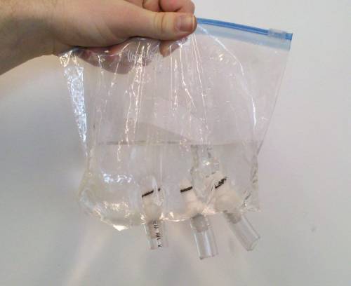
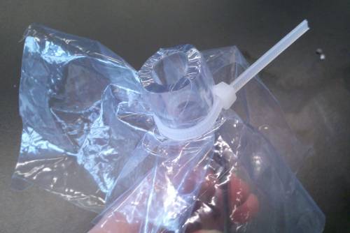
Attaching and Sealing Fittings to the Bag The first picture below shows three panel mounts successfully attached to a bag with no leaks through the seal. The sealing mechanism is simple and requires no equipment other than the bag, the fitting, and the hose: The bag is stretched over the fitting and then the hose is stretched over the fitting (with the bag already over it). A hole is then poked through the part of the bag which is over the fitting. The picture on the right shows the bag material stretched over a hose. A fitting would then be mounted to the hose, creating a seal between fitting and bag.
Protected Area
Some Useful External Links
Harvard Bioscience paper http://www.nature.com/nm/journal/v16/n8/abs/nm.2193.html
Picture of Harvard Rat Lung Bioreactor http://www.medgadget.com/archives/img/nqw34gvv.jpg
Picture & Description http://www.hugo-sachs.de/bath/il2_new.htm
Informal Discussion on Stem Cells http://science.howstuffworks.com/environmental/life/cellular-microscopic/stem-cell.htm
MedGadget Article http://medgadget.com/archives/2009/04/toronto_xvivo_lung_perfusion_system_for_better_organ_preservation.html
On Lung Function http://www.anaesthetist.com/icu/organs/lung/Findex.htm#lungfx.htm
Harvard Bioscience http://www.harvardbioscience.com/companies.cfm?show=hugo
Lung Info http://www.ehow.com/how-does_4924212_fetal-lung-development.html
