Project 2: Transmission Upgrade

The Transmission

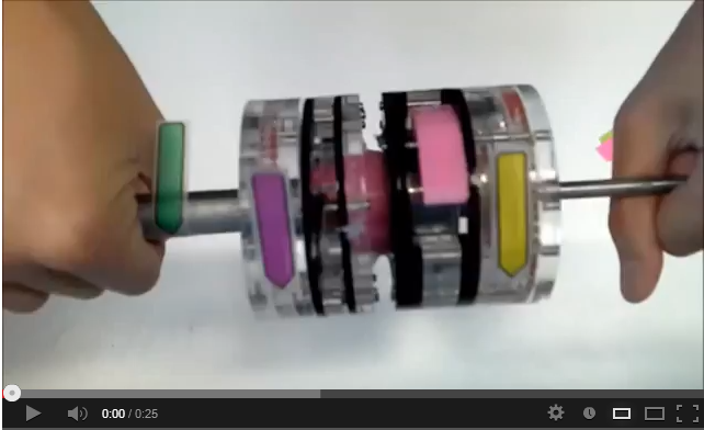
This is a picture of the model of the transmission we created. This transmission differs from others by not requiring cables to shift speeds; the rider pedals backwards to achieve such effect. Although there is another transmission which allows riders to shift speeds by pedaling backwards, our transmission differs by including three different speeds while the other has two.
Intro Video
Problem Statement
Current drivetrains are heavy, bulky, and/or require cables
Goals:
- Shift/brake without cables
- 2+ speeds
- Light weight
Design Ideas
- automatic shifting internal hub
- with coaster brakes
- mounted on single side triangle/rear stay (in conjunction with single blade fork)
- retro-direct drive
with two chains and reverse internal gear hubkeep pedaling forward - variable length cranks by four-bar linkage or spiral cam
- automatic shifting derailleur
Background Information
To influence our transmission, we took apart two others: a traditional three-speed transmission and a Kickshift transmission. We looked at the three speed transmission and learned how to incorporate three speeds into our design. A Kickshift transmission allows the rider to shift between two speeds by pedaling backwards, so it helped us rid our design of cables.
Planetary Gears

A planetary gear set consists of sun, planetary and ring gears. Any of the gears can be the driven (forced to rotate)to induce rotation in the others. The driven gear is the input. The input in a bike comes from the pedals. One of the other gears is the output which is the back wheel in a bike. Based on what is the input and what is the output, different gear ratios can be achieved which will cause the output to spin either slower, faster, or at the same rate of the input. For example, if the planetary gears are the input and the ring gear is the output, the ring gear will spin faster than the planetary gears. By changing the input and output of the planetary gears in a transmission, the bike can shift speeds.
Three-Speed Transmission


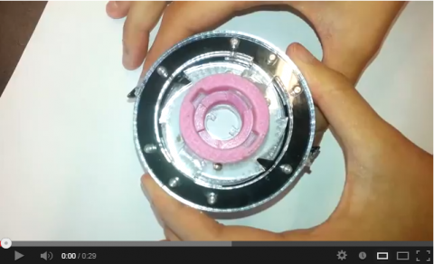
The pictures above show the inside of a three-speed transmission. The circled part is a dog clutch which is normally pulled or pushed on by the transmission cable which is what we're trying to get rid of. The dog can sit in three positions but only two are shown. The third position is in between the two shown. The dog pushes on the pawls (a picture of pawls is shown below in the Kickshift section). The position of the pawls corresponds to the three speeds of the transmission; so, the position of the pawls control what speed the rider is riding in.
KickShift


In the Kickshift, the position of the pawls are controlled by the saw tooth spline (third picture). One end of the pawl catches on the saw tooth. The depth of the cuts in the saw tooth are different so depending on which cut the pawl catches on, position of the pawl is different.


There are two different depths for the saw tooth cuts which alternate, one deep and the other shallow. The deep cuts correspond to when the pawls are out and the shallow cuts correspond to when the pawls are in. The left picture above is the former case and the right picture is the latter.
When the rider pedals backwards, the saw tooth moves back relative to the pawl carrier, which is how the transmission cable is eliminated. In the shallow position, these pawls are retracted and do not catch on the grooves of the hub-shell (shown below), so the pawls driven by the slower planetary carrier catch and drive the shell. In the deep position, these pawls are extended and catch on the grooves. Again, the position of the pawls control what speed the rider is riding in. The pawls which catch on the grooves of the shell drive the wheel at the speed the pawls are geared at. Since there the deep and shallow cuts alternate, there are only two positions the pawls can be in; so there are only two speeds on the Kickshift transmission.

Final Design
The final design that we came up with is based off of a traditional three-speed transmission and a Kickshift transmission. The design is allows the user to pedal backwards to shift between different speeds which is similar to the Kickshift design. Each time the user pedals backwards, the gears shift. The transmission has three speeds which is similar to the traditional three-speed transmission.

The transmission has two sets of planetary gears (above) which give it three different speeds. Two speeds come from one of the sets of gears and the third speed comes from the other set. The clear acrylic circle behind the gears is the planetary carrier. Both sets of gears have a planetary carrier which moves the planetary gears. The pedaling motion is the input that turns the planetary carrier which turns the planetary gears.

There are two sets of pawls modeled for our transmission (see above). Because of the gear system, the two sets of pawls move at different speeds and both move a a different speed from speed of the pedals. Each set of pawls corresponds to a different speed on the transmission (see below). The set of pawls on the driven planetary carrier was not modeled since they should always be extended and would not be directly affected by the shifting mechanism.
When the pawls are out, they catch on the hub shell. The hub shell is connected to the wheel. On a real transmission, there would be a third set of pawls that would be connected to the planetary carrier. The third set of pawls corresponds to the direct drive and those pawls would always be out. The fastest moving pawls that are out, move the hub shell, thus moves the wheel. Since the pawls on the planetary carrier move the slowest, they would be overtaken if faster moving pawls extend.
When the rider pedals backwards, the set of small pawls (left set of pawls) move along a saw tooth which is similar to the Kickshift transmission. The saw tooth in our design is different because there are two shallow cuts before every deep cut to correspond to three speeds. The pawls can either be in or out.
The center of the saw tooth is the cam which also has shallow and deep cuts. It also follows the two shallow cuts then a deep cut pattern. The cam rotates with the saw tooth. A cam follower (see picture below) fits into the cam. The cam follower moves up and down depending on which cut it's sitting in.


The cam follower pushes a bearing up and down. When the cam follower is up, the bearing pushes on the pink pawls and retracts them. When the cam follower is down, the bearing releases the pink pawls and torsion springs drive them out. When the pink pawls are out, the black pawls are in the one of the shallow cuts, so they are in. The pink pawls provide the third speed.
Thus, we created a transmission that does not use cables to shift speeds and has three speeds.
To see our SolidWorks files, Cad files, and pictures of the two transmissions we took apart, click here: https://www.dropbox.com/sh/af3ik5qne5dzlp4/23Jb3XtwYM
Assignments
Drawbot Competition 2013


Objective
The goal of this project was to use two stepper motors, an Arduino, and any other materials to create a robot that will draw a triangle. The competition was to see which group's robot could draw the triangle the fastest.
We designed our Drawbot to be a rotating arm where the distance from the pen to the motor could be varied.
Results
Official Time to draw triangle: 1:27
Although our Drawbot didn't win the class competition, it was the most creative and unique idea that drew a triangle. Most of the other groups used the same idea where two strings linked the two motors to the pen.
Issues: The Drawbot drew a triangle during the competition but the triangle wasn't in the lines of the triangle outline because the pen wasn't placed in the right starting position. There was a strut on the far end of the arm for support. There was too much friction between the strut and the table so the arm didn't move as smoothly as is should have. Improvements:
Some improvements we could make are: 1. Use stronger, larger motors 2. Build the arm out of something more durable than foam board 3. Reduce friction between the strut and the table or find a way to completely remove the strut
Code
#include <AFMotor.h> #include <math.h>
int i; int RpmB; int RpmT; float k; float theta;
int R; int StepsB; int StepsT; AF_Stepper motorT(64, 1); AF_Stepper motorB(64, 2); float b; float m; int u; int x;
void setup() {
Serial.begin(9600);           // set up Serial library at 9600 bps
Serial.println("Stepper test!");
delay(3000);
//motorT.release();
motorT.setSpeed(200);
motorT.step(2700, FORWARD, DOUBLE); //1st vertical line
for (i=0; i<100/k; i++) {
  k=1; //Steps taken by bottom motor per loop
  RpmB= 100; // Rpm of bottom motor
  RpmT= RpmB*4/3 ;//4*tan(theta)*RpmB/cos(theta); //Rpm of top motor
  motorT.setSpeed(RpmT);
  motorB.setSpeed(RpmB);
  theta = k*2*3.1415/2048*(float)i  ; //angle relative to starting position of arm
  R = 80/cos(theta);
  StepsB=k;
  StepsT= 1;  //steps taken by top motor
                             //80/cos(theta)*tan(theta)*k/2;    //
  motorT.step(StepsT, BACKWARD, SINGLE);
  motorB.step(StepsB, BACKWARD, DOUBLE);
  //Serial.println(StepsT);
}

for (i=100; i<250/k; i++) {
  k=1; //Steps taken by bottom motor per loop
  RpmB=100; // Rpm of bottom motor
  RpmT= RpmB/2 ;//4*tan(theta)*RpmB/cos(theta); //Rpm of top motor
  motorT.setSpeed(RpmT);
  motorB.setSpeed(RpmB);
  theta = k*2*3.1415/2048*(float)i  ; //angle relative to starting position of arm
  R = 80/cos(theta);
  StepsB=k;
  StepsT= //steps taken by top motor
            80/cos(theta)*tan(theta)*k/20;
  motorT.step(StepsT, BACKWARD, SINGLE);
  motorB.step(StepsB, BACKWARD, DOUBLE);
  Serial.println(StepsT);
 }
 for (i=250; i<370/k; i++) {
  k=1; //Steps taken by bottom motor per loop
  RpmB=100; // Rpm of bottom motor
  RpmT= RpmB/3 ;//4*tan(theta)*RpmB/cos(theta); //Rpm of top motor
  motorT.setSpeed(RpmT);
  motorB.setSpeed(RpmB);
  theta = k*2*3.1415/2048*(float)i  ; //angle relative to starting position of arm
  R = 80/cos(theta);
  StepsB=k;
  StepsT=  //steps taken by top motor
           80/cos(theta)*tan(theta)*k/20;
  motorT.step(StepsT, BACKWARD, SINGLE);
  motorB.step(StepsB, BACKWARD, DOUBLE);
 }
delay(3000);
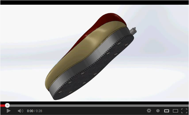
SolidWorks: Fleet Cleat
The following is the design we created in SolidWorks and Rhino for a shoe with retractable cleats. The shoe can be used for sports and normal daily use.


House of Quality
https://docs.google.com/file/d/0B04PQ0RiT5qSVmFkUnc5LTV3Mk0/edit?usp=sharing
https://docs.google.com/file/d/0B04PQ0RiT5qSXzZjM09OdUNESE0/edit?usp=sharing
Gantt Chart
https://docs.google.com/document/d/1qUcyOfSMw-G6kOPv77pNF6IXHcnYtC4gsfikLs4OT5w/edit?usp=sharing
https://docs.google.com/spreadsheet/ccc?key=0AkZN4Z6v8VjWdHBxbERqaG5KakNObzNrbG90N21vYUE#gid=0
Needs assessment
- lightweight: material choice, elimination of derailler, chain(?), and cables from drive train
- cableless gear shifting: modify internal gear hub
- cableless braking: modify coaster brakes
- integration with folding mechanism: modify transmission
Availability Schedule
| Monday | Tuesday | Wednesday | Thursday | Friday | |
|---|---|---|---|---|---|
| 9-10 | TS,JL | EVERYONE | TS,JL | JA | JA,AC,TS |
| 10-11 | TS,JL | TS,JL | JL | JA | JA,AC,TS |
| 11-12 | JA,AC,TS | TS,JL | JA,JL,AC | EVERYONE | |
| 12-1 | esc* | JA | EVERYONE | JA,AC,JL | TS,JL |
| 1-2 | JA | AC,JL | TS,JL | ||
| 2-3 | TS,JL | JA,AC | AC,TS | ||
| 3-4 | JA,AC,TS | AC,TS,JL | JA,AC | AC,TS | EVERYONE |
| 4-5 | JA,AC,TS | EVERYONE | JA,AC | JA,AC,JL | EVERYONE |
| 5-6 | EVERYONE | TS,JL | JA | EVERYONE | |
| 6-7 | JA,AC,TS | JA,AC,TS | EVERYONE | EVERYONE | |
| 7-8 | JA,AC,TS | Meeting with Mike | JA,AC,TS | EVERYONE | EVERYONE |
| 8-9 | EVERYONE | EVERYONE | EVERYONE | EVERYONE | EVERYONE |
Asterisk * for fluctuating availability.
exc = except