To build the tester, the mechanical components need to be made from the plans below. The actual assembly is very straight forward and intuitive, but you can use the gallery for reference photos.
One note is the upper loading platen and the platen spacer have 4-40 tapped holes to join the two parts together with a .25” piece of 4-40 threaded rod coated in loctite or some epoxy. You can get this threaded rod by just cutting a section of a 4-40 screw off.
The bottom loading platen is a salvaged glass hemisphere. This gives the tester a self leveling ability. However no commercial source of the glass is known so you will need to design the bottom platen part around a hemisphere you find or make it flat and lose the self leveling.
Ultramotion Digit Stepper Actuator with Tube Bracket
2 feet 3030 style 80/20 extrusion. Making the pillars 12 inches seems a little short, so rather than making 12 inch pillars with feet to get the height needed, you could buy 4' of stock and make 15 inch pillars for the tester. This costs a lot more so the funky feet fix was chosen.
16 compatible T-Slot nuts for the 3030 style extrusion
Aluminum and plastic stock as needed to make parts
Feet for tester: McMaster 23015T63 need 4 (1 pack)
Screws for crossbars: McMaster 92210A585 need 16 screws
Screws for mounting motor: McMaster 92196A276 need 4 screws
Screws for mounting LVDT Block and screw to salvage 4-40 tread from for upper platen: McMaster 92196A302 need 3 screws
Screw for mounting load cell and set screws for bottom loading platen: McMaster 92185A537 need 3 screws
For the screws, there is a good chance you may have something that will work laying around, or something that may just need to be hacksawed down.
The electronic components needed are:
Macrosensor PR-750-200 LVDT
Macrosensor LVC-2500 (theoretically better) or LVC-2401
50 or 250 gram load cell (Honeywell parts 060-1426-02 and 060-1435-03)
A “Model GM” signal conditioner (get from same place as load cell since they will know what signal conditioner is needed)
GekoDrive G203V Stepper Driver
TI-6211 data acquisition unit (DAQ), though any TI DAQ with a counter output and pulse generation could be used.
Data Sheets for Electronics
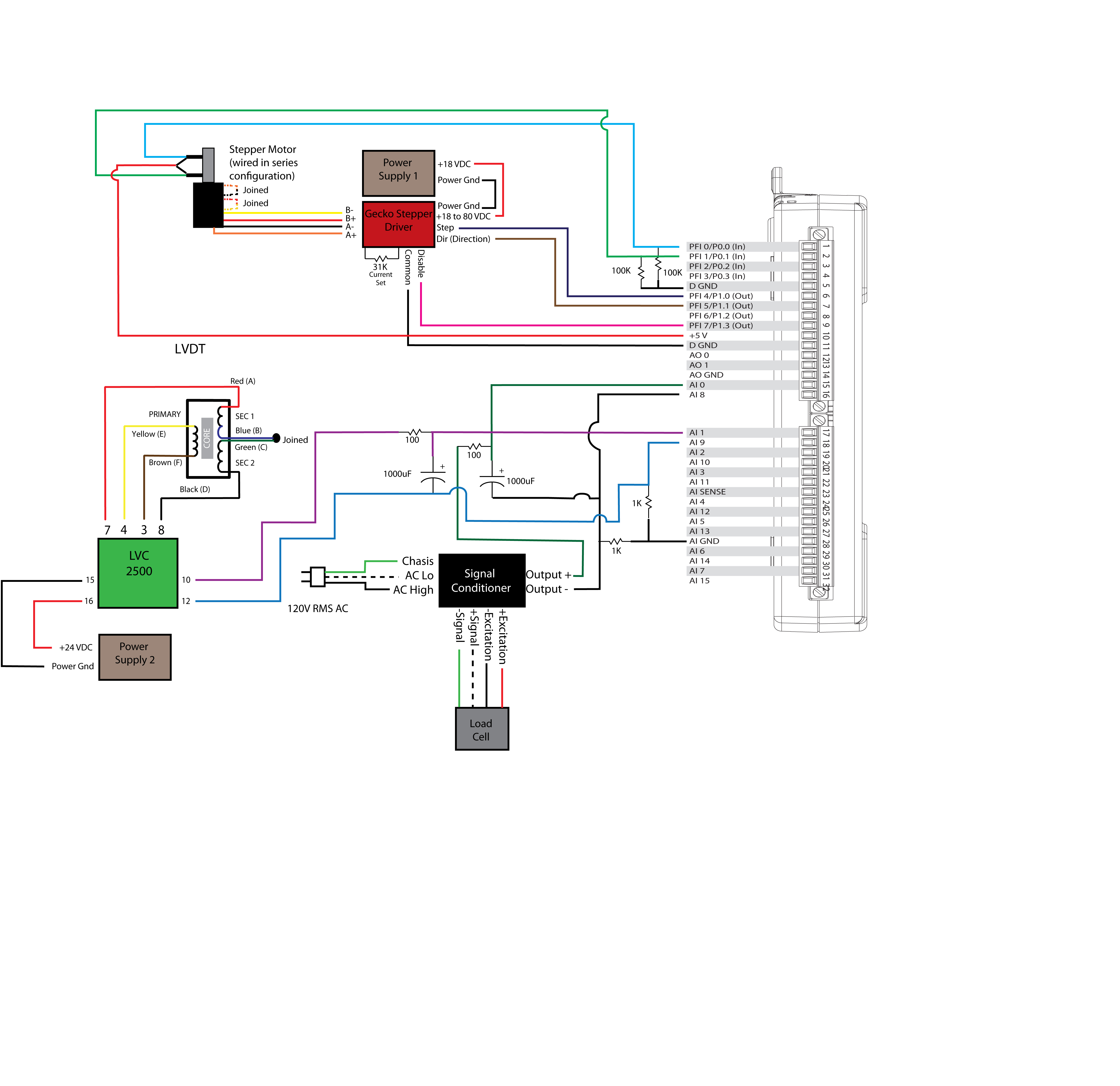
Use the wiring diagram to connect the electronics and daq together. A breadboard may be needed to include some of the resistors and capacitors.
Wiring Diagram