EID 101: Design & Problem Solving
Shifter Group: Sergio Rodriguez, Gavin Kaplan, Amy Chambers, Wilfrido Castillo
Introduction:
The shifter group was tasked with the designing, machining, and implementing of a mechanical shifting system. This year’s design focuses on optimization, reliability, and flexibility of the system so it can easily adapt to changes made year to year by the team. The final design consists of three components;
- 1) Shifter lever
- 2) Shifter stick
- 3) Push-pull cable
Shifter Lever:

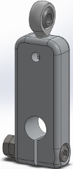
The purpose of the shifter lever is to convert the linear travel of the push pull cable into a rotational displacement necessary to shift. The motion of the driver actuating the shifter stick causes this linear displacement which results in angular displacement of the gear shift axle, controlling the current gear engaged.
In the figure of the shifter lever above, the bottom hole is used to press fit the lever onto the gear shift axle. On top there is a rod end that allows the push-pull cable to come in at an angle and reduce the crimping of the cable while still providing enough linear displacement to cause the necessary angular displacement.
Shifter Stick

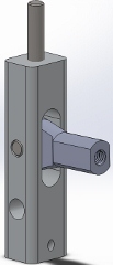
The shifter stick connects to the push pull cable via a rod end, again to prevent crimping of the cable. When the shifter is rotated forwards or reverse it will displace the cable which actuates the gear shift axle off the engine. This shifter stick was made to minimize the size of the shifter and to allow for interchangebale shifter knobs, according to the driver's preference. The shifter knob is attached to the shifter lever via set screw on the top portion.
Shifter Knob

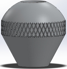
This shifter knob is designed to be interchangeable according to driver preference. This current design is the base knob, its dimensions were driven by comfort level of the driver and how well the driver can grip the shifter knob. The knurled portion of the shifter knob is necessary to provide the driver extra grip necessary to hold on during high speed turns.
Assembly

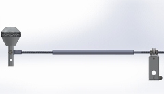
The figure above displays, in essence, the final assembly of the mechanical shifter system. On the actual 2013 Cooper Motorsports Formula Car installation of the system was made difficult due to the tight space constraints from the various other subsystems right next to the engine, these tight constraints made it difficult to fit the proper tools required for installation. The results of the shifting system is still pending; Our system will be tested in the Michigan FSAE competition in 2013.