Problem Statement
Our gumball machine is a new take on the classic candy dispenser. The game is kicked off by a 3-axis controllable claw to choose the gumball. What follows is entirely up to the player. Each of the moving parts inside the machine is linked to controls on the front panel. The result: no two runs are quite the same, except, of course, that the player always receives the coveted gumball.
Work in Progress

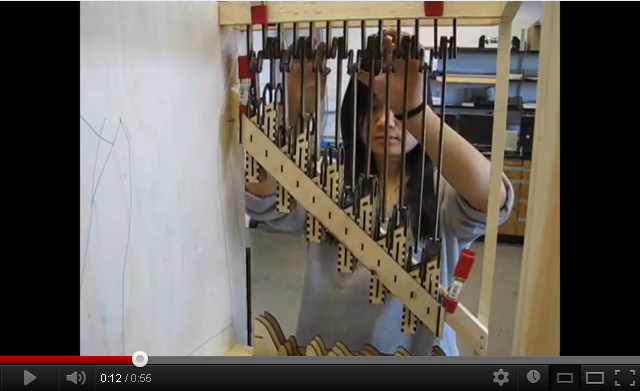
Watch the lift running!


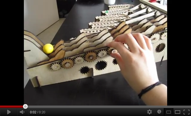
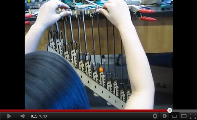
The full petal conveyor, geared and everything.
The flip flops now have user control. Behind each flip flop is a servo motor controlled by the Arduino and some push buttons.


Getting ready to mount the lift onto the frame.
 '
'
Petal conveyor. Experimenting with gear meshing.
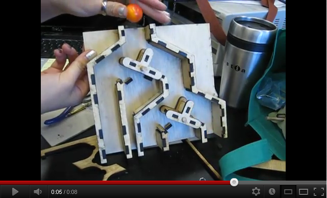
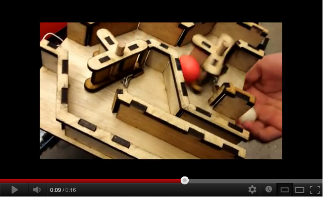
Watch the flip flops!

Flip flops. Incidentally, they make a sort of binary counter


Slow prototyping..


Added back, bottom, and leg supports.
Testing the hacked micro servo with laser cut gears.


Hacking a micro servo motor. The very top gear has a plastic nub that prevents the shaft from rotating continuously. Inside the housing lives a rotary potentiometer that sends the Arduino board information about the servo shaft's location in terms of varying resistance. We cut the potentiometer wires and replaced them with two resistors.

Color sensor for the first stage of the gumball game.

How the RGB LED colors split up.


LEDs for the color indicators.

Here, we're testing one of the lift gears with a DC motor that we pulled out of a broken printer. It probably needs a gear reduction to slow it down.


Click to watch some component testing!


One of the gumball gear lifts. The gumball will slip between two gear teeth, riding up the gear while supported by two external wire rails. The tab-and-slot construction and the back extension will both stabilize the gear (keeping it perpendicular to the axle) and mesh with a driving gear attached to a servo motor.


Crankshaft assembly. Over-engineered for maximum vertical support.

The spacer bar keeps things even. Lap joints work better than expected with the material.


The first two towers were made too narrow by mistake. The new ones are wide enough to fit the gumballs comfortably.

The flip-flop seems to work best if the initial angle is less than 45 degrees.

More laser cutting!

Frame for the final gumball machine casing.

Prototype for the penguin lift steps. Crankshaft and crankpin models coming soon.


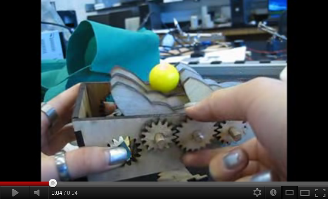
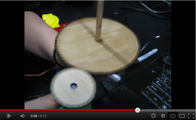
Prototype for the final conveyor that gives you the gumball. The petals are kept aligned with an axle key. Elmer's glue seems to work well enough.

This is the setup for the new color sensor. Currently, it is showing that when the color sensor detects green, there is a digital output and the green LED will turn on. If the color sensor detects any other color (Red, Blue, or Clear/White), then it will not output any digital values and no LED will light up.

The contacts on the back of the color sensor evaluation board to show input/output(SCL and SDA for input and LED as possible output). SCL and SDA are clock and data respectively for communication purposes. There are also the ground and power contacts.

We laser cut this box out of 0.175” plywood to test how it would hold up as a building material. The corners are joined with box joints, and the inner faces are joined by tab and slot. Both joint types seem to work well.
The three holes on each face were cut at .125, .130, and .135 inch radii to test how they would work with 1/4” dowels, considering that the laser kerf is not quite negligible on small scales. It turns out that the .125” hole gives a snug fit (part and axle turn together) and the .130 hole lets them spin freely. The last hole is too large to be useful.

This is the CAD layout we sent to the laser cutter to begin prototyping the machine components.


These are drafted components of the petal lift and the wheel lift that will be transporting gumballs.

This is the CAD drawing for one portion of the penguin lift. The pieces were drawn meshed together to save material and ensure that the joint would not be too snug.

The user will control each flip flop to determine whether the gumball goes on or falls to the bottom.


Here, we have determined the placement of most of the machine components so that the gumball paths run properly.


We made this skeleton to get a better sense of the physical scale of the machine, as well as to determine the layout of the machine components.


A model of one of many planned gumball lifts. The wire crankshaft moves alternate pistons up and down.
watch the gumball lift in action!


Early Design Sketches


Timeline
Work on this project will continue into the summer. Here is a proposed timeline.

