Introduction
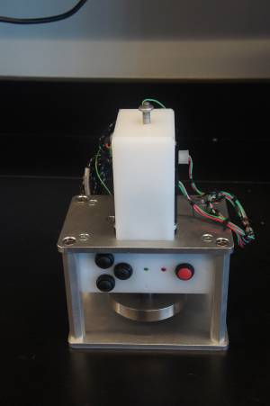
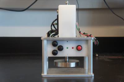
The mechanical loader was designed by Keith Yeager of Columbia University for repeated compressive loading of biological tissue samples. Its compact, standalone design allows it to be run inside of an incubator, so that the sample's environmental conditions (temperature, humidity, sterility) can be closely controlled.
Design
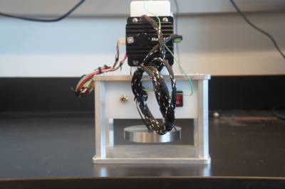
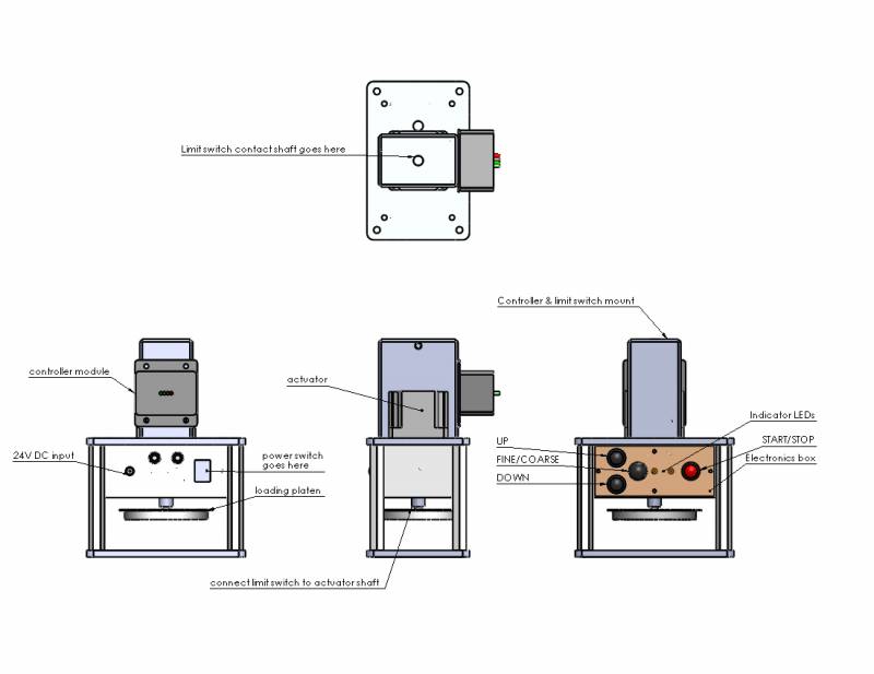
The loader is designed around the Haydon Kerk 57H4A-3.25-815 linear actuator, and its driver module, the Haydon Kerk PCM4826X programmable stepper motor controller. Using readily available (“off-the-shelf”) components simplifies design requirements and eliminates the need to 'reinvent the wheel,' so to speak.
The loader's structural frame consists of two aluminum plates with four hexagonal aluminum standoffs sandwiched between. The top plate acts as a mount for the electronics box, the actuator, and the driver mount / limit switch assembly.
The loading platen is made of machined stainless steel (alloy?) to optimize biocompatibility and minimize corrosion.
The electronics housing is machined from nylon, eliminating issues with electrical conductivity and minimizing weight.
The driver mount is machined from nylon as well, as it would otherwise be excessively heavy and expensive.
Electronics & Controls
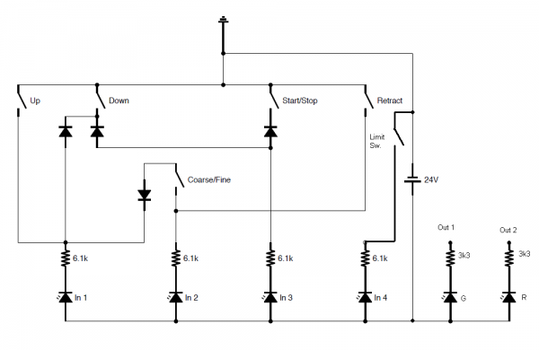
The above image is a schematic of the controls and indicator LED outputs. The “Retract” switch was not implemented but may be in future builds. In1..4 are the controller's 4 digital inputs (optoisolated) and Out1..2 are the controller's first two digital outputs. The controller's digital outputs are all open-collector.
The [stepper motor controller] is designed to allow the use of separate, isolated power supplies for powering the motor and the control interface; all of its digital input/output communication lines pass through optical isolators. As no dangerous voltages are used, this precaution was deemed unnecessary and so the entire unit is powered from a single 24-volt supply.
The loader has a basic set of controls - UP, DOWN, START/STOP, and FINE/COARSE movement selection. The device is programmed via USB using Haydon Kerk's IDEA software; this software also allows the actuator to be controlled manually.
* UP & DOWN - Move the platen up and down
* FINE/COARSE - Adjusts the step size of the UP/DOWN controls
* START/STOP - Starts and stops the compression cycles
The actuator's motion is constrained by an electrical limit switch, consisting of a rod positioned above the shaft of the actuator and the shaft itself. These are electrically connected to the driver module, which stops the actuator if it detects the switch closing. This reduces wear on the actuator from repeatedly jamming into the end of its range of travel. Additionally, it sets a reference position to 'zero' the actuator.
The controller has four optoisolated digital inputs and four open-collector digital outputs; this is more than the number of inputs the device possesses (four switches (UP, DOWN, FINE/COARSE, STOP/START) AND a limit switch). The limit switch is given its own input (IN4), leaving three inputs free; the signals from the four switches are encoded into three bits using a diode logic circuit. While convenient, the diode logic configuration does have drawbacks; if both “UP” and “START/STOP” are pressed, the controller 'sees' the combination of inputs corresponding to the “DOWN” switch. While proper operation does not involve pushing more than one button at once (and so the unit's functionality is not impaired), this unintended behavior can be hazardous to an unsuspecting user.
Two of the controller's four digital outputs operate indicator LED's on the unit's control panel. One LED illuminates if the loading platen is in its zero position, and the other illuminates when the programmed compression cycle is running. As the controller's digital outputs are software-controlled, the LED's can be repurposed by adjusting the code installed in the controller.
Operation
Connect the unit to a 24-volt DC regulated power supply capable of sourcing at least one amp. A female barrel-jack connector for this purpose is located on the back of the unit next to the master power switch.
Power on the unit.
[next???? i guess the next steps really depend on what is in the code]
