Open Source Hydrostatic Pressure Loader
In tissue engineering, it is often desirable to be able to cyclically load cell cultures under hydrostatic pressure. To fulfill this task, researchers at Mount Sinai Medical Center have designed and built a hydrostatic pressure loader mostly out of off-the-shelf parts. While this device works quite well, it has the limitation of requiring an Instron tester to actuate it. Our goal at Cooper Union is to design a new method of achieving similar loading conditions without being tethered to expensive Instron equipment.
Summary of Construction and Use
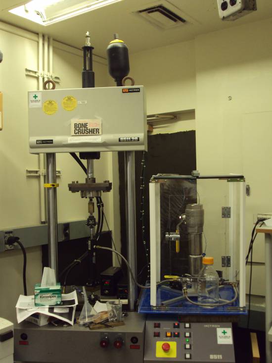
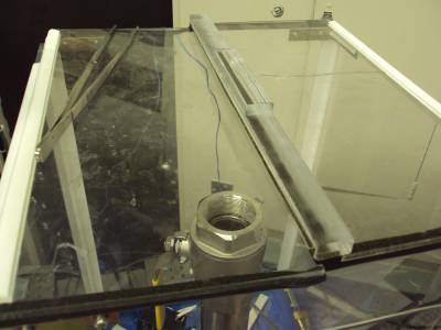
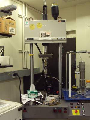
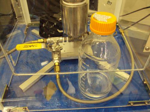
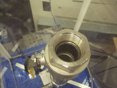
The setup consists of the pressure vessel itself, a piston, and an incubator. In the current setup, the piston is mounted on an Instron mechanical tester. A Teflon hose braided with stainless steel runs from the piston to the pressure vessel to transfer pressure. There is also a valve at the base of the pressure vessel which can be opened to release water from the system if there is either excess water or if the water is being replaced entirely. Warm water is loaded into the vessel from the top. A ball valve at the top of the pressure vessel is used to close the vessel when testing is in process. An acrylic incubating chamber surrounds the pressure vessel and contains heating elements to ensure that test samples remain at body temperature.
A thermocouple inside the incubator is connected to a process controller to regulate the temperature, and a pressure sensor at the base of the pressure vessel is connected to a process meter to give a pressure reading. Since the Instron mechanical tester measures loads, not pressure, the pressure in the pressure vessel is controlled indirectly by varying the load.
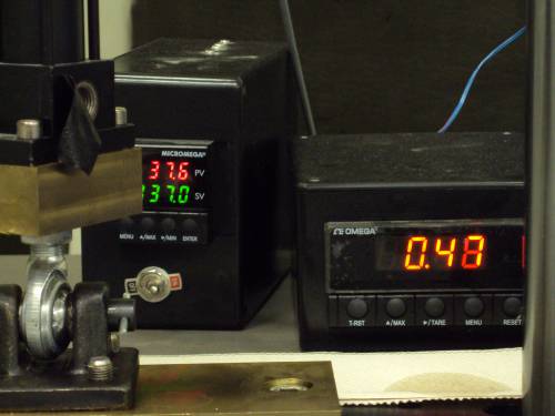 Thermocouple controller (left) and pressure meter (right). | 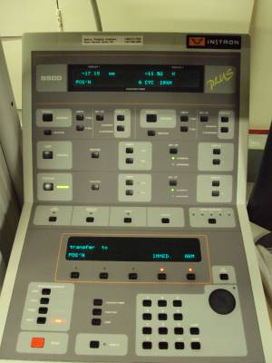 Instron control panel. |
When an experiment is run, the pressure vessel is first filled from the top with deionized water that has been microwaved to a temperature slightly higher than human body temperature. Before beginning the test, the pressure and temperature of the system have to be normalized. Cell cultures in a bag containing the required cell media are then loaded into the pressure vessel. At this point, testing is ready to begin.
Short video clip of the piston being actuated: http://www.youtube.com/watch?v=-atjP03BKNI
Construction
Since the hydrostatic pressure loader was originally built for Mount Sinai's use almost entirely out of off-the-shelf parts, schematics and assembly instructions were never drafted. To facilitate the construction of a new hydrostatic pressure loader, I have provided the original bill of materials with purchase links, photos of the setup, and descriptions of how each part should generally be assembled.
Bill of Materials: hydrostatic_parts_list.xls
Piston
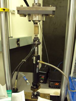
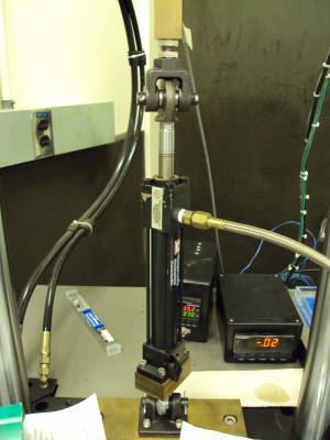
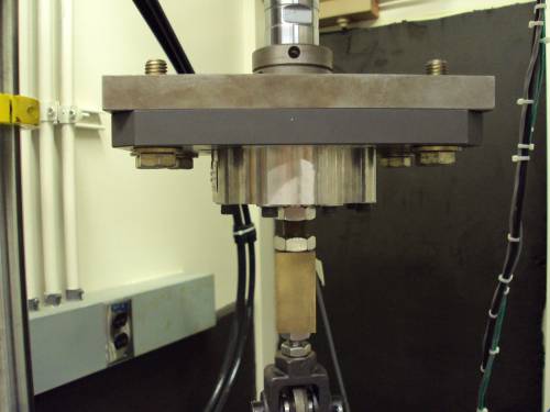
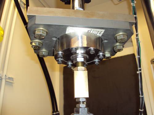
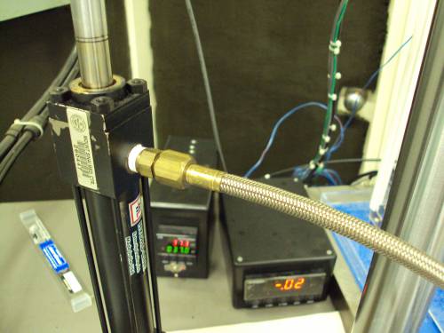
The main components of the piston assembly were purchased from Hydro Air. Holes were drilled into sections of brass bars which are used to mount the piston to the Instron. The piston is held between a clevis fastener at the top and ball joint rod ends at the bottom. A Teflon hose end is fitted to the outlet near the top of the piston cylinder.
 |  |  |
 |  |
 |  |
Incubator
The incubator is simply an acrylic enclosure with a hinged ceiling so it can be opened from the top. Angle brackets can be purchased to hold together the corners of the enclosure; they are not listed in the bill of materials however. Mount Sinai's pressure vessel incubator also has a front door, which requires additional components to construct. Panel hinges line the corners of the enclosure to seal in warm air.
The key part of the incubator is the heating system, which consists of a warmer, a cooling fan for the heater, a thermocouple, and a process controller. Keeping the incubator warm is simply a matter of correctly wiring the electronics. Phil Nasser, who constructed the entire pressure vessel apparatus, also recommends to use fuses in your setup to protect it against current overdraw.
Pressure Vessel
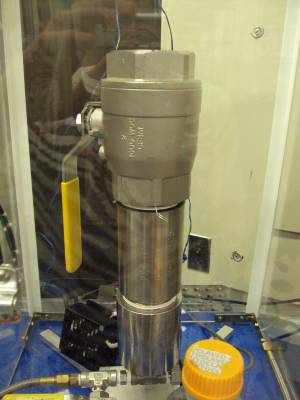
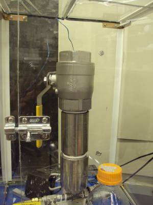
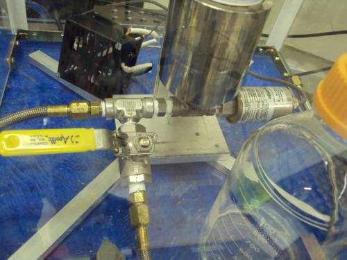
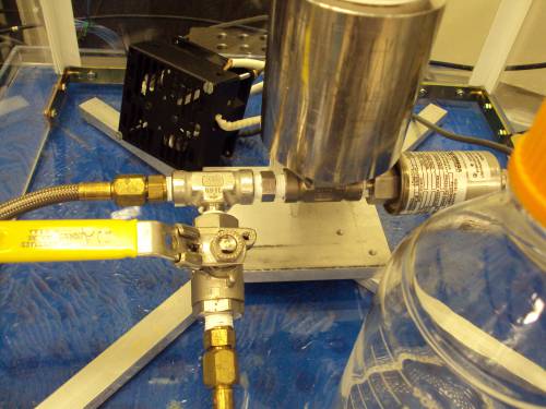
The pressure vessel is essentially a very large ball valve mated with a pipe section. A reducer is used to mate the 2” diameter pipe section to a tee fitting. The pressure sensor mates with a pressure snubber, which also mates to the tee fitting. This tee fitting is connected to another tee fitting, which is connected to the Teflon hose that leads to the piston and to a release valve. The release valve has a section of Teflon hose connected to it, which water flows through when the pressure vessel is being emptied.
 |  |  |
 |  |
 |  |
Experimental Protocol
As Word document: hydrostatic_testing_procedure.doc
Video demonstration on YouTube: Hydrostatic Pressure Loader use demo
LabView DAQ code: daq_code.zip
Acknowledgements
Although Cooper will work to develop a better way to actuate the system, the original system was developed entirely at Mount Sinai, and so the following individuals are credited for the development of the pressure vessel and thanked for their collaboration:
- Philip Nasser, who built the device.
- Karl Jepson, PhD, a PI at Mount Sinai Medical Center who helped conceptualize and design the device.
- Hui B. (Herb) Sun, PhD, a PI at Mount Sinai Medical Center who helped conceptualize and fund the device.
- Evan Flatow, MD is the head of the Orthopaedic department at Mount Sinai Medical Center (Leni and Peter W. May Department of Orthopaedics).
- Clare Guterl, who demonstrated the pressure loader in use and allowed us to photograph it.
