Digital Logic Design
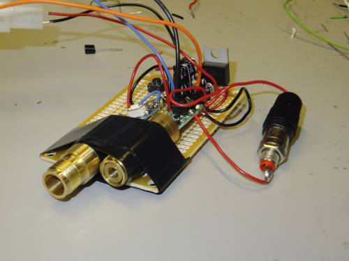
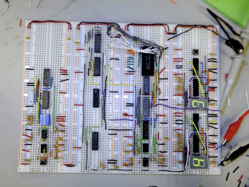
As part of ECE150(digital logic design), I was part of a group to develop and build a laser tag system. This system was comprised of two, separate devices. The first was the gun itself. Using a series of switches, the user selects one of 8 unique gun ID's. Using that number, the gun transmits a unique signal in the form of light pulses. (This is similar to how television remotes work!) The second component is the receiving unit (or “vest” in typical laser tag systems). The reviving unit receives the incoming signal via a photo transistor system, and the signal is decoded using on-board logic. The system then records the hit, and assigns a point to one of the user's respective team. Each team's score is recorded on a seven-segment display.

