Group Side-Projects
This page is dedicated to the IR Water Mark's group projects that are not related to their semester-long project.
Drawbot Competition
Stepper Motor Testing
Video of our simple stepper motor testing: http://youtu.be/-yGPs-rVxMg
Description of major components
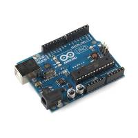
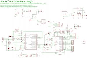
Arduino:
This is a micro-controller which is ridiculously easy to program. It is open source and has become extremely popular due to its flexibility and it's ease of use. The Arduino UNO was used to control the stepper motors in this exercise. It contains an ATmega328 and has 14 digital in/out-put pins, 6 analog inputs. It operates on 5 Volts with 32KB of memory and with a max clock speed of 16 Mega-Hertz. No previous experience is necessary since the programming of the board is simple, especially since code can be found on arduino.cc/forun/ already made by the Arduino's extensive and extremely helpful community.
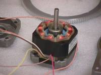
Stepper Motor:
Instead of continuously spinning like DC motors or rotating to specific angles like servo motors when powered, stepper motors rotate specific fractions of revolutions called a “step.” The convention for stepper motors is for one step to be equivalent to 1.8 degrees, or 1/200th of a full revolution. Using a microcontroller, such as an Arduino, a stepper motor can be programmed to rotate to very precise locations. This is accomplished with the use of electromagnets. Mounted to the central shaft of the motor is a magnet in the shape of a gear, where each tooth is slightly offset from electromagnets that surround interior of the motor. By providing power to one of these electromagnets, magnetic attractions are induced and the gear rotates 1.8 degrees to align a tooth with an electromagnet opposite its polarity. By providing voltage to different electromagnets at different rates, the gear will spin the motor shaft at a desired angular speed, direction, and magnitude of revolution. These specifics are determined by which of the 4,5,6 or 8 wires protruding from the motor are connected to power at any given instant, a complicated process that is ultimately controlled by the Arduino microcontroller.
For the drawbot competition, the stepper motors are on obvious choice. Since they allow for incredibly precise manipulation, drawing a shape becomes a function of the number of steps rather than determining angular displacements of DC motors in specific timer intervals. Two stepper motors will be used in the competition and will be used to rotate pulleys that guide the ropes, which support the pen. Although it requires more programming than just delivering power to a motor, it will be much easier to get the mechanics of our drawbot to function properly.
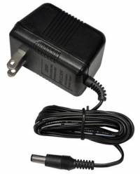
Power Supply:
The power supply is responsible for allowing the Arduino to function and to output voltages to power the rest of the drawbot setup (i.e. the motor shield and stepper motors). Although the Arduino itself can operate with only the power coming through the USB connection to the computer, about 5-6 volts, connection to a 9 volt power source is necessary to control the stepper motors. Consequently, after uploading the program, the Arduino must be connected to a 9 volt source directly from a wall outlet or to a 9 volt battery pack. Since the drawbot will have to be hung on the wall, a battery pack must be used to avoid the inconveniences of plugging into a wall outlet while still being able to deliver the appropriate voltage to the stepper motors. Without the power supply, the entire drawbot setup would be entirely useless.
Motorshield:
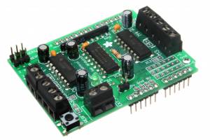
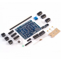
The arduino is specially designed (with exposed connections) to allow it to be connected to add-on modules, such as a motor-shield. The shield used was purchased from adafruit.com and was assembled by the group. The motorshield allows up to two stepper motors to be controlled by the arduino and possesses connections which allow 2 servos to be connected to the arduino. Along with multiple resistors, and capacitors, 3 integrated circuits were soldered on to the motorshield. There is a 74HC595N with is a shift-register whose primary role is to add additional pins to the original 14 the arduino has. Using at minimum 4 arduino pins(to send data, clock, and clear), this shift register adds 8 I/O pins. It doesn't seem like much but additional shift registers can be added onto this one with out sacrificing anymore of the arduino pins. The other two ICs are both L293D which are Dual-H Bridge Motor Drivers, one for each stepper motor or for each 2 bi-directional DCs motors. These driver chips, unlike many others, have integrated kickback-protection diodes which reduces the risk though it reduces the maximum current as well.
Code:
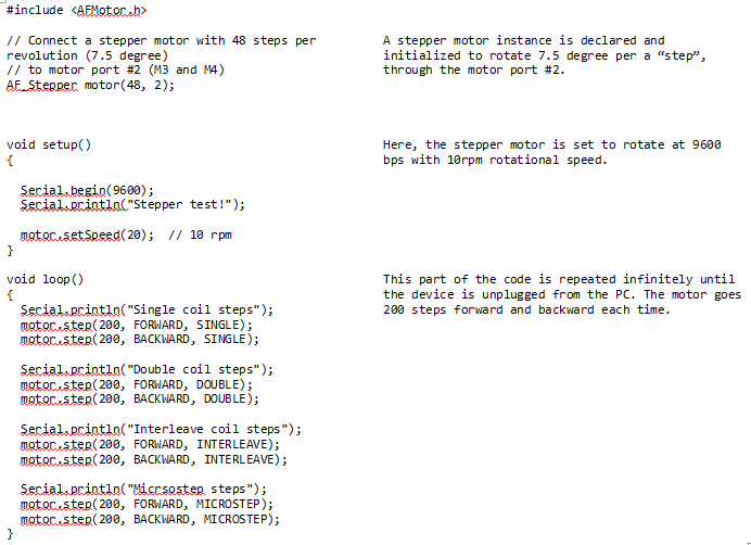
Code is written in the Arduino application “Arduino 1.0” and uploaded to the device through the universal USB port. It allows us to control the device easily without understanding its mechanism in detail. There are open API libraries on the web that programmers can easily consult with to write codes for various tasks. Limitless code packages are also available on the web that facilitates coding for specific, advanced tasks. Here's our code for this week's simple stepper motor test, with a brief explanation for each block.
SolidWorks Bed
Renderings and Animated Motion Study
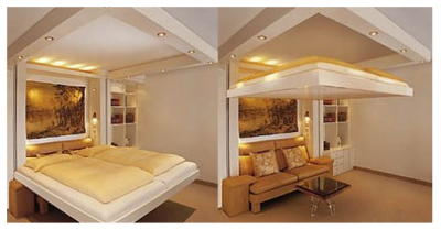
Our bed design uses ropes that move through pulleys to lift the bed. Because the ropes cannot be modeled in SolidWorks they do not appear in images and video; however, the specific ropes to be used are listed in the Bill of Materials. The optional desk serves as a counterweight for the bed. The desk by necessity is just slightly heavier than the bed and can be folded up for when the bed is supposed to be on the ground.
Video of our motion study: http://www.youtube.com/watch?v=R16llH9krEw
Click here to see a few images.
Bill of Materials
House of Quality
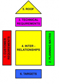
The current HOQ includes Bed Up's approach to the problem. Empty columns are present so that we may import and compare ratings from other groups too once they have created their HOQs.
house_of_quality_for_bed_peter_ascoli_ir_water_mark_eid103_2_house_of_quality.pdf
