Pump system with cylindrical chambers
Back to allograft preservation page
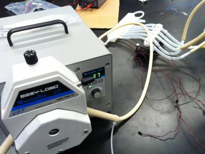
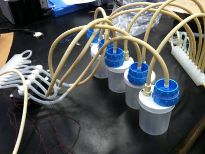
Picture 1. || 2. Masterflex peristaltic pump for input media || Overall setup
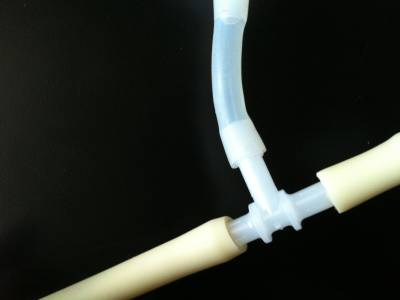
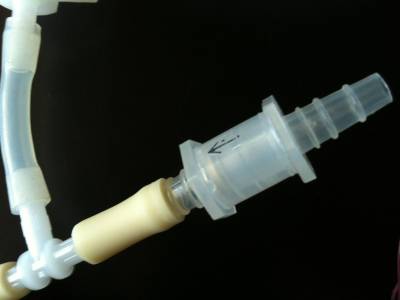
Picture 3. || 4. 3 way T-connector that connect media input and air-intake to valve manifold. || Air intake with a check valve that prevent media from leaving the system through air-intake
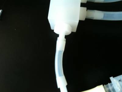
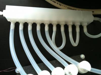
Picture 5. || 6. Input valve manifold || Layout of valve manifold - solenoid valve rack
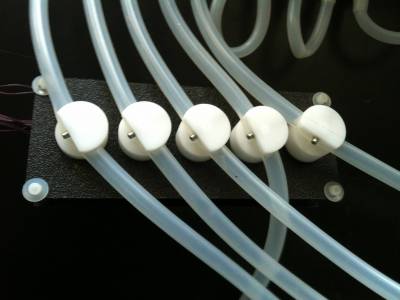
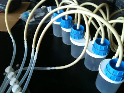
Picture 7. || 8. Solenoid valve rack || Solenoid valve and cylindrical chambers connected (into blue input filter holder)
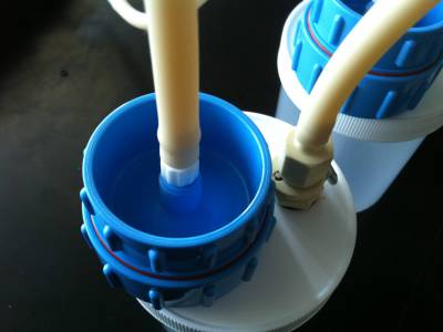
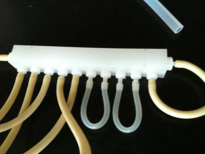
Picture 9. || 10. Filter holder (input) || Output valve manifold
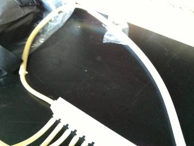
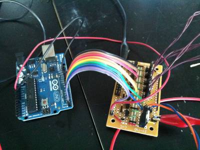
Picture 11. || 12. Output valve manifold to output tube that will be used for second peristaltic pump || Arduino control unit
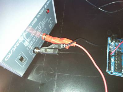
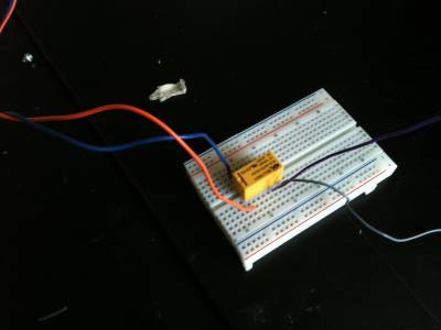
Picture 13. || 14. Power supply || Relay to operate the pump