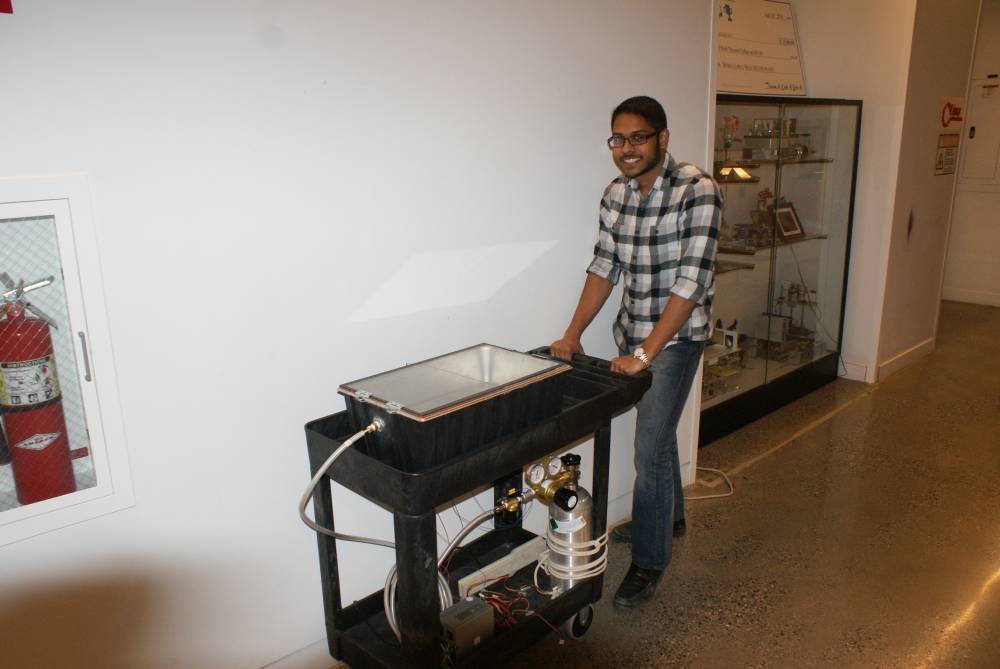
Open Source Portable Tissue Strip Incubator
Introduction
The intersection between the biological sciences and engineering has great potential to solve many medically-relevant issues. Currently, research for these issues demands advanced testing systems for biological materials. One such piece of equipment used in biological engineering research is the bioreactor. A bioreactor may refer to any engineered device or system that sustains a biologically active environment.
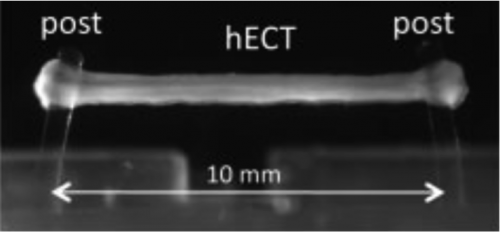
Bioreactors are currently in development at the Costa Laboratory in the Icahn School of Medicine at Mount Sinai for the parallel fabrication, maintenance, and testing of engineered cardiac tissue (ECT) strips. In these high-throughput bioreactors, ECTs are stimulated by an externally applied voltage difference to the samples at various pulse frequencies. Additionally, the device acquires real time data by measuring the force of contraction and threshold potential of the sample. These samples, about 8 mm in length, serve as a testing system for in vitro cardiac tissue models and drug screening.
ECTs must be contained within a biomimetic environment for the duration of a drug screening study. Existing incubators can simulate this environment, but are not suitable for the bioreactors being developed at Mount Sinai. The incubators cannot support real-time data acquisition, media exchanges, or drug applications. Once closed, they seal off any connection from the outside, allowing the user no interaction with the test samples. In addition, existing incubators are large stationary devices that must be opened to transport samples, consequently disturbing the biomimetic environment inside and increasing the chance of contamination. The goal of this project is to design a portable, stand-alone incubator system that can house the bioreactors containing ECTs for periods as long as one month, without disturbing their natural environment. The incubator will be modular, allowing for different types of bioreactors to be utilized for various experiments. Other features will include real-time data acquisition, sensing, and control.
Functional Requirements of Incubator Design
Overview
Baseline requirements for incubators involve control of three specific process variables: carbon dioxide, temperature, and relative humidity. Specifically, cardiomyocytes require an environment of 5% CO2, 37 degrees centigrade, and 95% humidity. Significant deviation from these set points are harmful to the biological environment, and could ruin an experiment by producing inaccurate results or even cell death. The following descriptions describe each functional requirement in detail:
Sterility
Maintaining stem-cell growth and keeping tissue samples healthy requires that the bioreactors are kept in an environment similar to that found in the human body. This requires that the incubators have specific functional characteristics. The first of these functional requirements is sterility. During any experimentation involving biological materials and processes, organic samples must be separated from the outside environment to prevent contamination. Sterility must be considered during the entire lifespan of the incubation system. During experiments, the incubator will not be opened unless it is moved to an already sterile environment. Therefore, sterility only needs to be considered when the incubator is completely closed. Additionally, all components interacting with the samples or with any fluid interacting with the samples must also be sterilized between experiments.
Temperature
Secondly, the tissues’ environment must maintain a temperature of 37 ±0.5oC. To simulate their natural environment, the tissues must be kept at the temperature within most mammalian bodies, 37oC. If the cells are exposed to a temperature outside .5oC of reference temperature, they will act differently than they would in the human body, and the data acquired during testing will not be accurate. While lower temperatures decrease the metabolism of the cell, higher temperatures run the risk of denaturing metabolic proteins and could lead to apoptosis.
Cell Culture Media Exchange
Cell perfusion is another concern in the incubator design. The ECTs are surrounded by media to provide the nutrients necessary for cell growth and health. Over time, however, these nutrients are catabolized, and excreted waste from the cells builds up in the media. Consequently, the media must be replaced on a regular basis to provide fresh nutrients and remove waste that could damage cells to keep the ECTs alive for longer periods of time. The current protocol involving ECT perfusion is a half media exchange twice a day, allowing for tests of up to 30 days. Media exchanges are programmed to occur regularly throughout testing within this incubator, setting it apart from existing incubators.
Relative Humidity
It is important that the environment within the incubator remains at 95% relative humidity. If the humidity drops below 95%, the media will begin to evaporate too quickly and the osmotic equilibrium in the cell’s microenvironment is disrupted.
Carbon Dioxide
The CO2 levels are required to be at 5% in the gaseous mixture above culture media. This carbon dioxide level is critical to maintain a physiological pH in the media itself. This is vicariously occurring through a vapor-liquid equilibrium between the bicarbonate buffer system in the media and the vapor above it.
Cells metabolize glucose and excrete waste products (CO2 and water). According to the literature, “Advancing functional engineered cardiac tissues toward a preclinical model of human myocardium”, the tissue strips are exposed to Dulbecco's modified Eagle medium (DMEM) five days after production. Depending on the type of DMEM used, there is a sodium bicarbonate or HEPES buffer system in culture media. These buffer systems resist changes from physiological pH values. There is also a visual indicator in the media, which turns from red to yellow once the pH becomes too low from excreted CO2 waste buildup.
The buffer equilibrium is detailed below:

The cellular waste pushes the equilibria towards an acidic direction (to form carbonic acid, or hydrogen ion and bicarbonate). However, maintaining the undissolved CO2 (g) levels at 5% can mitigate the progression of an acidic culture media solution. Particularly, these gaseous dynamics are governed by Henry’s Law.
In addition to the functional requirements which facilitate cell growth and life, there are also requirements for the patented high-throughput bioreactors and for novelty of the design. The first is to have a standalone system that transports the portable incubators. Portability is a critical part of this design. When tissue strips are transported in a lab, they are taken out of their biomimetic environment. Most incubators are stationary, and a user is required to transport tissue samples from an incubator to a sterile examination hood for experimentation, which drastically increases the risk of contamination. The incubator design will have the ability to move around the lab, and be placed directly within the examination hood, which maintains the biomimetic environment the entire time. In order to fit within the examination hood at Mount Sinai, incubator must be smaller than 18”x24”.
Sensors and actuators are attached to the bioreactor and incubator and need to be connected to a power source and a computer for the user to acquire real-time data. Because existing incubators are sealed off from the outside environment for sterility, they do not allow for wires to connect sensors within the incubator to the data acquisition system outside. This incubator must allow wires to connect the sensors and actuators inside the incubator to a display and control panel outside.
Modularity is also critical to the design of this incubator. The incubator’s novel modular design allows for a variety of bioreactor types to be placed into a single portable system. This is a feature that is not available in current portable incubator designs because they are over design with the size and shape of a particular bioreactor or cell chamber in mind.
Incubator Design Process
Step 1: Choosing an Inner Shell
Stainless steel will line the inside of the incubator. Other materials were considered, but stainless steel has the most desirable qualities relative to other options considered (aluminum and various polymers).
The most desirable quality of stainless steel is its corrosion resistance. This is due to the “passive, chromium-rich complex, oxide film that forms naturally on the surface of the steel.”1 This layer is about 1 to 2 nm thick and prevents the steel from corroding when interacting with the outside environment. Not only does this layer shield the metal from the environment, it also shields the environment from the metal. The alloying components of the metal, such as chromium and nickel, are sealed within the metal by the passive layer. The amount of alloying components released from stainless steel is negligible.
While corrosion resistance is desirable, aluminum and most plastics share this quality. These materials are generally cheaper than stainless steel, but were still not chosen over stainless steel for a few reasons. The first reason is hardness. Stainless steel is harder than aluminum and plastic, and will be less prone to scratches and dents. For example, the Brinell hardness of stainless steel 304 is 1232, while the Brinell hardness of Aluminum 6061-T6 is 953. Scratches and dents are very undesirable because they provide a cavity for microorganisms to gather and grow, which can contaminate the incubator and the experimental samples contained within.
Stainless steel has another quality that sets it above aluminum and plastics: sterility. Studies have shown that after cleaning with dishwasher detergent, 97% of microorganisms were eliminated from stainless steel, while in polymers, between 79% and 84% remained. Similarly, tests have shown that “microbiological residues on stainless steel are only about ⅕ of those on aluminum and much less than on fluoropolymers.”1 Stainless steel is so easily cleaned that it has been compared to glass and porcelain. This quality implies that cleaning the incubator will be simple, and the incubator will be less likely to house and microorganisms that would contaminate any experiments being performed inside.
Because stainless steel is superior to other materials in medical applications, its use has been regulated by ISO, the International Organization for Standardization (recognized in the United States). According to ISO regulation ISO 7153-1, stainless steel is the material to be used for surgical and dental instruments1. This further encourages the use of stainless steel for the lining of the incubator. Stainless steel is the standard for medical equipment, and that practice should be continued in the design of this incubator.
Other desirable qualities of stainless steel include being rust proof, high heat resistance, recyclability, being non-magnetic, and not staining. In addition, variations in stainless steel alloying components can make it easier to machine and weld.
Step 2: Choosing the Insulation
The next step is to prepare the insulation so heat can be applied directly to the inner shell, and not be released outside of the system.
The insulation for the incubator is aerogel. Aerogel has a high k-value, which decreases the thickness needed to insulate the incubator. While aerogel is more expensive than most insulation materials, the cost is offset by the space saved. Because the incubator is portable, it is designed to be as compact as possible. Aerogel allows the user to insulate the incubator without sacrificing a significant amount of space.
Step 3: Choosing the Outer Shell
The outer shell houses the insulation and the inner shell, and packaging the two in a neat and aesthetically pleasing format.
This outer shell also functions as another thermally resistant layer. Poly(propylene) plastic material an ideal material for the outer shell because it will act as an insulator, durable enough to avoid breaking during transportation between labs, and cheap.
Step 4: Choosing the Sensors
The three values that need to be monitored in an incubator are the temperature, CO2, and humidity. The K-33 BLG 30% CO2/Temp/RH Data Logging Sensor is ideal because it monitors these three values, and is designed for incubators.
Step 5: Choosing a Controller
The incubator requires a simple means of control to actuate systems such as the thermal and CO2 system. An Arduino Uno is ideal as a controller because it is relatively cheap, small, and contains both analog and digital I/O.
Step 6: Designing the Thermal System
The heating systems typically used in existing incubation systems are air jackets and water jackets. Air jackets involve a fan blowing air over a heating element to distribute heat quickly. This method is best for recovering air temperature after the incubator is opened. One disadvantage to this system is the large number of movable parts which increases the need for maintenance in case of failure. Additionally, a filter is required to prevent contamination. This solution does not seem ideal for the system because the incubator is not expected to open during tests, and therefore will not need to recover temperature quickly. The water jacket holds heat for longer periods of time. However, it is much heavier due to the mass of the water, requires regular “topping off” of the jacket itself, and may need to be drained if the incubation will travel long distances.
Because these two existing systems are not ideal for the portable tissue strip incubator, it leaves the opportunity for a novel and more cost effective solution to heating. This incubator uses nichrome wire and Kapton® Polyimide Tape as a heating system, similar to the heating system used in the base plates of 3D printers. Nichrome's high resistivity [insert resistivity] causes it to heat up significantly when a current is passed through it. The Kapton® Polyimide Tape prevents the wire from short-circuiting with the stainless steel inner shell.
When a 12V is applied to the nichrome wire of this length, it has a steady-state temperature of [number] degrees Farenheit. This is much higher than the desired temperature of 37 degrees Celcius, so an on-off control is implemented. The hECT's [talk specifically about hECT's?] cannot reach 42 degrees Celcius, so a hysteresis value is chosen at 39 degrees Celcius (to account for the ±1 C of the sensor). The lower bound is set at 35 degrees Celcius.
Step 7: Choosing the Power Supply
The incubator receives power from the a standard 110V outlet, but 110V is too large for this application for numerous reasons. Firstly, the sensor requires 5.5V - 12V DC. Secondly, the heating system was designed with a 12V power source. If 110V was applied to the nichrome wire at this length, it would melt. Thirdly, the Arduino Uno requires 5V. Finally, the solenoid valve used in the CO2 system requires 12V.
In addition to a PSU, a Uninterrupted Power Supply (UPS) will also be integrated into this system. This allows the user to unplug the unit and transport it to another lab without losing power to the entire system.
Step 8: Designing for a Fluid System
Certain samples in this incubator might require media exchange; living organisms will need nutrients to brought in, and waste products to be brought out. To allow for media exchange, there must be ports that connect the inside of the incubator to the outside environment, while maintaining sterility. This is done by making holes, lining them with grommets, and sealing any open space within the holes with wax.
Step 9: Designing for Humidity
Heat must also be applied to maintain the humidity within the incubator. There are two methods of humidity regulation in existing incubators: passive and active humidification. This bioreactor uses passive humidification. Most passive humidification systems use a water pan as a source of water. When the passive system is heated it increases or decreases the relative humidity inside the incubator. This incubator will have water directly on the bottom of the incubator [explain why], as oppose to having it within a separate water pan. Silver particles will be added to the water to prevent microorganisms from growing within the water, eliminating the need to replace the water.
Step 10: Designing CO2 System
A CO2 tank is required to maintain a 5% CO2 level within the incubator. The smallest size for a medical grade CO2 tank, size D, is used to allow the system to maintain portability. A solenoid valve is actuated by the Arudino that allows the flow of CO2 into the incubator, and a regulator valve controls the flow rate.
Step 11: Designing for Modularity
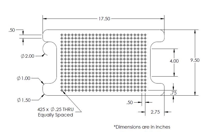
The immediate application for this bioreactor is to be used with bioreactors being developed by Mt. Sinai Hospital that house hECT's. In order to expand the scope this incubator, it is designed to hold items that will house living organisms, such as petri dishes. A shelf inside the incubator has a grid pattern with 1/4” holes. Any device that has 1/4” pegs can be placed on the shelf and tested in the incubator.
Another feature of this incubator that allows modularity includes the grommet holes. These can be used in the fluid system, or sealed if a media exchange system is not necessary. They can also be used for air diffusion and data acquisition.
Step 12: Designing a Lid
The client at Mount Sinai requested a lid be designed such that the user can look inside the incubator to visually examine the specimens. The lid is divided into two pieces such that handling the lid would not be a cumbersome process. [explain better] Borosilicate glass is used because it very thermally resistive relative to other types of glass.
Step 13: Designing for Portability
The entire system is placed on a cart that enables the user to easily transport the incubator and samples between different labs.
Assembly
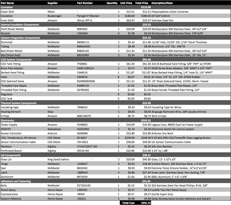
Step 1: Obtain Raw Materials
In order to build the incubator device, one must purchase the following materials
Step 2: Outer Shell Assembly
- Adjust Height: Using nichrome wire attached to a power source (e.g. 32 SWG with 12 V), melt a line in the polypropylene box to shorten the box as needed (approximately 5” shorter for this box).
- Holes: Melt holes in the plastic for the CO2 line and the grommets with a soldering iron, or another hot tool. Place the grommets in the corresponding holes.
- Latch: Attach the bottom portion of the latch to the outside long sides of the outer shell. The location does not need to be exact, they only need to be towards the center and symmetrical with each other.
*USE A FUME HOOD WHEN MELTING THE PLASTIC*
Step 3: Inner Shell Assembly
- Holes: Drill holes for the CO2 input and the grommets with a hand drill. Place the grommets in the corresponding holes.
- Brackets: Glue the brackets to the inside of the shell with Loctite Epoxy Metal/Cement. Placement does not have to be exact, because the brackets can be bent after they are glued to ensure that they are level and all four remain in contact with the shelf.
- Sealant:
- Line the top of the lip with 1/4” wide silicone rubber strips. The strips should create a 24.25” x 10” rectangle.
- Hinges:
- Cut four slots in the lip of the incubator, on the shorter sides.
- Drill and tap holes in the metal baseplates for the hinges. The holes must be tapped in the pattern that they appear on the hinges. T
- Glue baseplates to the outside of the inner shell, underneath the holes cut in the lip, with the Loctite Epoxy Metal/Cement.
- Cut vertical slots in the hinges. This allows the user to adjust the height as necessary when attaching the glass to the hinges.
- Attach the hinges to the baseplates with 1/4-20 screws.
- Heating Elements:
- Lay Kapton® Polyimide Tape on the outside of the shell, along the bottom and the two longer sides.
- Lay the nichrome wire on top of the tape, and simultaneously place another layer of tape on top of the wire to hold it in place.
- Attach standard 22 AWG insulated aluminum wire (or something similar), approximately 2 feet, to the nichrome wire with crimps. These cannot be soldered because the solder will melt when the nichrome is heated. Use Scotch® Tape to organize the wires and by pressing them against the outside of the shell and organizing them such that they all meet on the middle-top portion of the long side of the outer shell.
The wire pattern on the two longer sides is shown below:
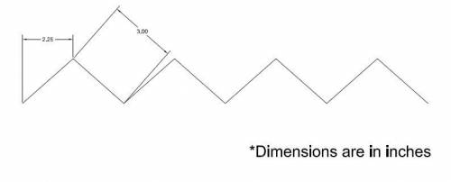 When assembled, it looks like:
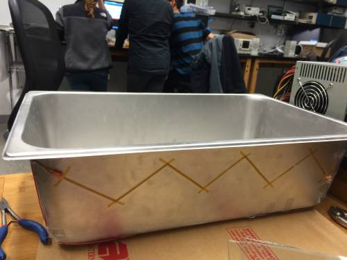 The wire pattern on the bottom is shown below:
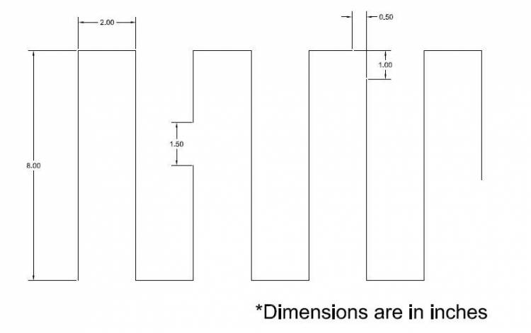 When assembled, it looks like:
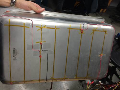
Step 4: Insulation
- Cut to Size: The pattern of the insulation is shown below. Cut two of each of the trapezoidal pieces (sides), and one of the rectangle (bottom).
- Sow: Sow the pieces together with standard thread (cotton, polyester, nylon, etc.).
- Holes: Cut the holes for the grommets and the CO2 input in the insulation. These can be slightly oversized.
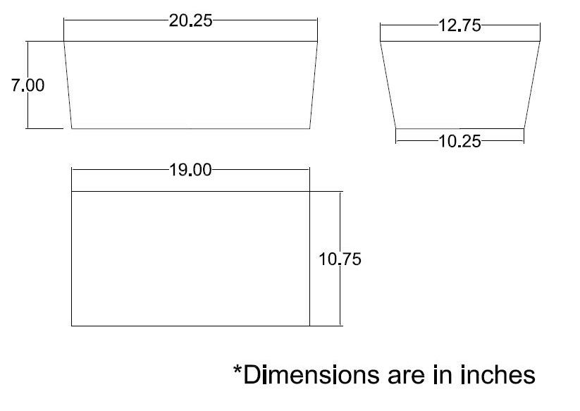 When assembled and placed in the outer shell, the insulation should look like the following (*no holes are shown in picture*):
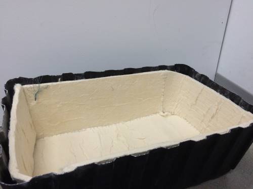
Step 5: PSU
- Black Wires: Find and strip three black wires, and attach an alligator clip to the end of two of them. These wires act as ground.
- Green Wire: Find the green wire, strip the end, and solder it to the end of the black wire without the alligator clip. This acts as an on-off switch. If the green wire is not connected to ground, the PSU will not turn on.
- Yellow Wire: Find and strip a yellow wire, and attach an alligator clip to the end of it. This wire provides 12 V.
- Red Wire: Find and a red wire, and attach an alligator clip to the end of it. This wire provides 5 V.
*DO NOT REMOVE THE CASING OFF OF THE PSU. HIGH VOLTAGE*
Step 6: Circuit
- Board: Drill holes in a piece of acrylic according to the pattern of the PCB and Arduino. This acrylic will then be mounted on outer shell.
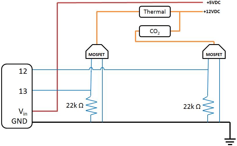
- Wiring: Wire the circuit as shown below:
Step 7: Shelf
- CNC: CNC the shelf according to the drawing below. The holes may need to be deburred.
Step 8: CO2
- Overall:
- Wrap all male-threading for CO2 System components with PTFE Tape.
- CO2 Incubator Assembly:
- Connect “3/8in to 1/4in brass pipe adapter” to outer end of the “stainless steel bulkhead tank fitting”.
- Connect “1/4in barbed tube fitting” to the “3/8in to 1/4in brass pipe adapter”.
- CO2 Tanks Assembly:
- Attach “CO2 Regulator” to “CO2 Tank”.
- Connect “1/4in female-female pipe adapter” to “1/4in male-male pipe adapter”.
- Connect “solenoid valve” to “CO2 Regulator” using the pipe adapter assembly.
- Connect “1/4in barbed tube fitting” to the “solenoid valve”
- Overall:
- Use hose to connect the barbed end of the CO2 Incubator Assembly to the CO2 Tank Assembly.
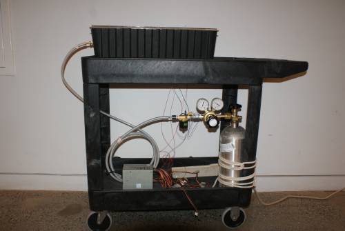
Assembled CO2 setup is below:
Step 9: Lid
- Cut to Size:
- The glass must be cut to 10” x 12” pieces.
- Cut the stainless steel 16 gauge stainless steel to 12.5” x .75”.
- Seal:
- Line the border of one side of each pane with 1/4” wide silicone rubber and glue with Gorilla Super Glue Gel.
- On the other side of one pane, line one 10” side with 1/4” wide silicone rubber, and the other pane with 1/4” wide 16 gauge stainless steel. (The stainless steel should overhang on each side by 1/4”, see diagram below)
- Attach two pieces of silicone rubber, 1/4” wide, stacked on top of each other at the end of the stainless steel
- Latch:
- Attach the 4 baseplates for the latch to the top of the lid. Be sure to align these with the portion of the latch already attached to the outside of the outer shell.
- Hinges:
- Glue the hinges to the lid.
Attaching the silicone to the glass should look like the following:
![]()
Step 10: Integration
- Grommets:
- Cut the 1/4” aluminum tubing to a length of 1.25”.
- Place the tubing inside the grommet holes.
- Seal the around the tubing and the grommets with Amazing GOOP®.
- Wiring:
- Pull the wiring from the nichrome wire through the appropriate hole in the insulation and the outer shell.
- Attach the nichrome wiring to the 12 V and ground cables.
- CO2:
- Fix “stainless steel bulkhead tank fitting” through the 1in hole in the right wall of the incubator.
- Final Seal:
- Glue the bottom of the stainless steel pan lip to the top of the outer shell.
