This code uses 74LS194 bi-directional shift registers that are shifting left. After each clock pulse, the data will move one bit to the left (q3 to q2, q2 to q1, q1 to q0, and serial left to q3). For more application the s0 and s1 pins of the chip can be controlled by the Arduino to shift right, hold, or parallel load (besides shift left).
Here is the datasheet
int clock=5;
//shifting left
int leftin=4;//serial left data in

void clocks(void);

void setup(){
  pinMode(clock,OUTPUT);
  pinMode(leftin,OUTPUT);

  digitalWrite(clock, LOW);
  Serial.begin(9600);
}
void loop(){
  digitalWrite(leftin,HIGH);
  clocks();
  digitalWrite(leftin,LOW);
  for(int i=0; i<3; i++){
    clocks();
  }
}

void clocks(void){
  digitalWrite(clock,HIGH);
  digitalWrite(clock,LOW);
  delay(500);
}
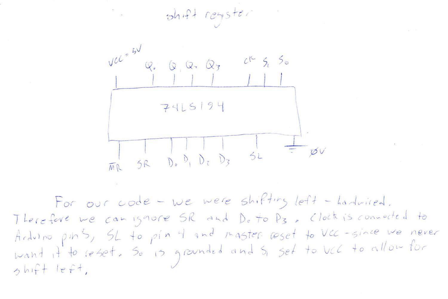
Here is the promised circuit diagram:
Except where otherwise noted, content on this wiki is licensed under the following license:CC Attribution-Noncommercial-Share Alike 3.0 Unported