Test Tube Spinner
Introduction
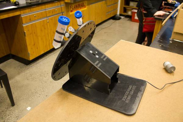
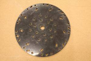
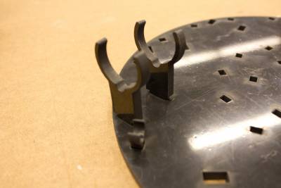
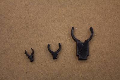
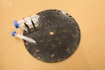
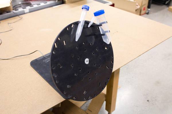
The test tube spinner is another open source laboratory equipment design. The design was created by Keith Yeager and a demo model was built at Cooper Union. The device is made from .25” laser cut ABS, a few basic electronic components, and a gear motor for rotation. The spinning plate can hold many test tubes but only three are shown on the plate in the demo unit due to a lack of ABS to make more clips for the plate.
Build
Parts
The parts can mostly be scrounged items. The following are needed to build the spinner.
- .25” thick ABS
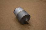
- DC Gear Motor
Jameco Electronics has a good selection of gear motors. The design can be adapted to work with almost any gear motor by changing the location of the screw holes that the face of the motor mounts to.
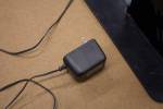
- Power Adapter
A 12V wall wart was used to power the gearmotor but any appropriate power source for the gearmotor can be used.
- Power switch
- ABS bonding glue
- 3/4” Plastic rod stock
Optionally to make the gearmotor adjustable speed, a TIP120 transistor and 10K potentiometer can be used to regulate the power sent to the motor.
Plans
We need to post the plans for laser cutting in DXF form. The power switch and motor mounting holes may need to be changed to suit what you have on hand.
Assembly
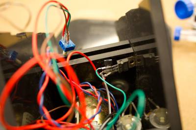
Wire the power supply, motor, switch, and optional speed control according to the circuit diagram below.
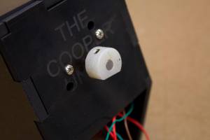
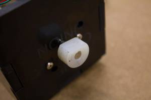
The motor gets mounted to the front piece using screws.
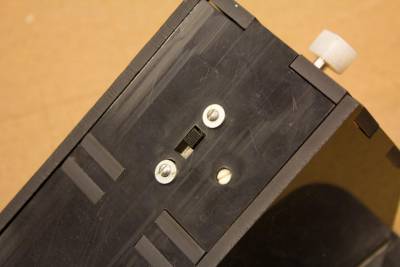
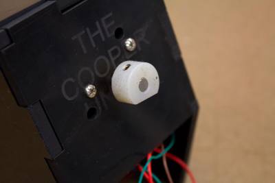 Then mount the switch and tuck away the wires. A potentiometer for adjusting the speed pokes through a hole in the top.
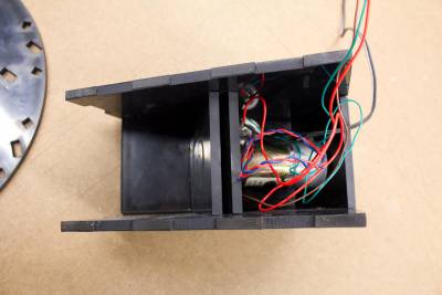
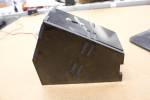
The rest of the spinner snaps together to form the enclosure and gets placed on the base. Unless the snap fit is very strong, some cement may be needed to hold the spinner together.
Base
Main box
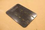
As seen below, the spinning plate and the motor must be joined in a way that can transmit a fair amount of torque. A D-shaped piece of plastic was made that uses a set screw to attach to the motor shaft and the spinning plate slides over. This was then glued together.
The test tubes press into the clips on the spinner plate.
