Development
After researching different types of trebuchets, two types stood out to us: The Floating Arm, and the Floating Axle King Arthur trebuchets. To figure out which trebuchet we would develop as a team, we broke up into two groups. Each group researched, designed, and built a scale model by laser cutting acrylic. Whichever trebuchet was able to shoot farther using similar material constraints would be deemed the winner and would be developed further.
Midterm Presentation Powerpoint
Floating Arm Trebuchet
About
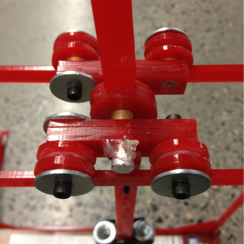
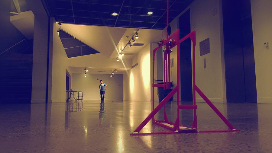
The Floating Arm Trebuchet (FAT) is one of many different types of trebuchet designs. A trebuchet is a type of siege engine used in the Middle Ages which features a counterweight as its main source of energy that drives a throwing arm. The FAT, unlike most other trebuchets, distinguishes itself by allowing the counterweights to drop perpendicular to the ground as opposed to around a specified point. These counterweights are usually located on either end of a rod whose motion is restricted by a track to strictly the direction perpendicular to the ground, as mentioned earlier. The counterweights and rod are located near the middle of the trebuchet when viewed from the side. To prepare for launch the counterweights would be lifted straight up and a trigger would prevent them from falling. When the trigger is released the weights fall downward due to gravity. Therefore, heavier counterweights and a longer falling distance will give the FAT more power. Connected to the counterweights is the throwing arm. The throwing arm is restricted as well, so as to avoid the arm from moving left or right when viewed from the front of the trebuchet. The arm is restricted by a similar track that is perpendicular to the direction of fall of the counterweights. Usually a rectangle, the track of the throwing arm has a wheel located on the top back corner of the body, which is the side farther from the throwing direction. The arm is allowed to rest around the wheel while cocked, and pivot around it when it is fired. Once the counterweights call in line with the track of the throwing arm, the arm begins to lose contact with the corner wheel. At this point a second wheel, attached to the arm itself, becomes the fulcrum of rotation until the projectile is released. When the counterweights hit the point where the arm is vertical, the arm will stall and thereby launch the projectile. Like all trebuchets, the projectile is placed in a sling which is connected to the end of the floating arm. Hence, the speed of the projectile can be increased by extending the length of the throwing arm. There are many benefits to the FAT. First, the machine is easy to prepare for launch because the counterweights only need to be lifted straight upwards and, by doing so, the arm would fall back into place. Second, the room for error is minimized by restricting the majority if the design with tracks. Lastly, the FAT, by using two separate fulcrums during a launch, can shoot farther because the arm travels farther than a regular trebuchet.
Development
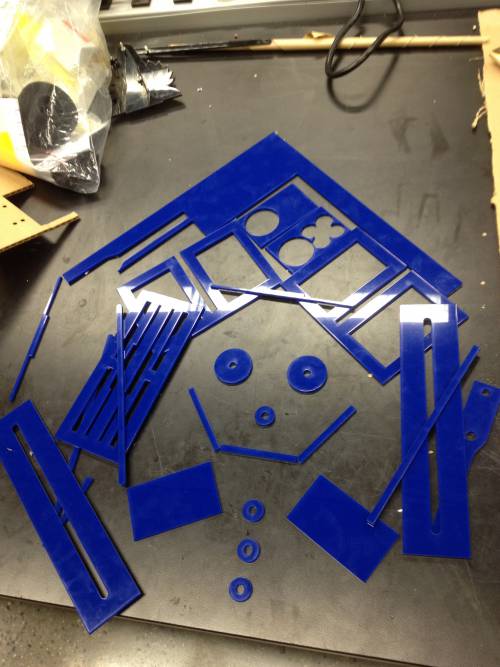
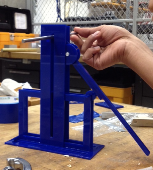
The following are pictures of the small model trebuchet we laser cut from a 12 x 12 inch 1/8 inch thick square of acrylic.
Floating Axle King Arthur
About
A Floating Axle King Arthur (FAKA) trebuchet differs greatly from both a standard trebuchet and even from a floating arm trebuchet. The support system of the trebuchet is nearly identical. Thus, any geometry may be employed provided that it can hold the system. Furthermore, the base must include a heavy counterweight, as the trebuchet is prone to moving during firing. However, a FAKA trebuchet has many more unbalanced forces during firing, and thus requires a much heavier counterweight. While a regular trebuchet and floating arm trebuchet both drop a counterweight from only slightly above their pivot points, a FAKA trebuchet drops a counterweight from nearly 2 arm lengths above the ground, giving it more potential energy, thus allowing projectiles to be fired a greater distance. Unlike other trebuchets, the FAKA has what is called a “floating axle”. This is a wheeled axle at the top of the support structure that is free to roll forward and backwards. This axle rotates freely, and the forward rolling motion it experiences during firing adds even more initial velocity to projectiles. Around this axle, there is another cylindrical structure that can rotate freely around the floating axle, but must move forward and backwards with the floating axle. Rigidly attached to this cylinder is the firing arm. This arm is extremely similar to other trebuchet arms. In one direction, it extends nearly to the ground, with a sling attached. In the other direction, a small amount of the arm extends. Other trebuchets attach a counterweight at this location. However, the FAKA trebuchet attaches a second arm at this point, free to pivot. This arm is nearly the same length as the firing arm, and the counterweight is attached to the end. Thus, the counterweight can be raised nearly twice as high on a FAKA trebuchet. When the counterweight is released, it rotates around the second (arm to arm) pivot point. After rotating far enough, there is a force imbalance, and the counterweight forces the floating axle to accelerate forward, and the firing arm to rotate. In this way, the FAKA is able to fire a projectile located in the sling.
Development
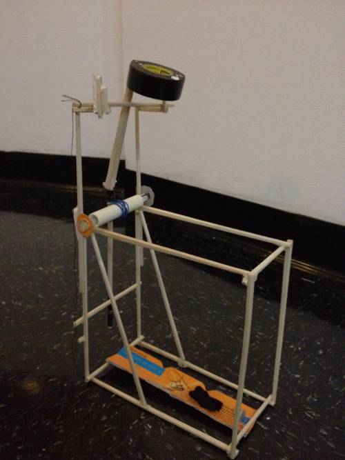
In attempting to design and develop a FAKA trebuchet, we realized the physics is extremely difficult to comprehend without being able to physically play with the trebuchet. Thus, we created a quick model out of random household materials like chop sticks, hot glue, a cereal box, etc. and were able to make a miniature model that can launch a projectile around 40 feet.
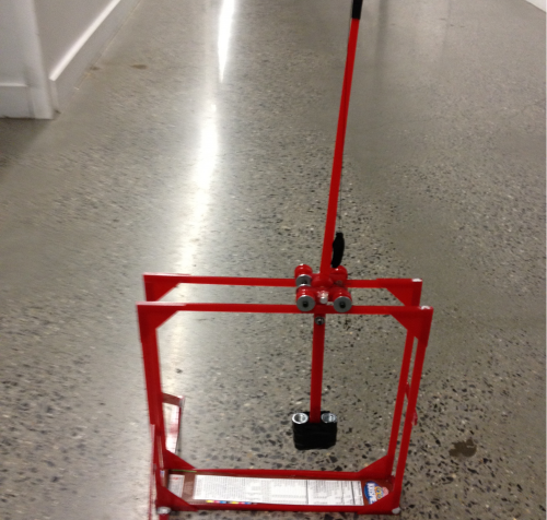
Using what we learned from the initial model, we then designed, and laser cut the parts for a trebuchet out of acrylic. Using a few spare parts like rods for axles, we assembled the trebuchet. Images are below.
