Digital Logic Design
Digital logic design is a project-based class that dealt with the use of basic logic components such as logic gates, shift registers, and Multiplexers. Here is a list of projects that I have done, including a short abstract and pictures of the final projects.
Project 1
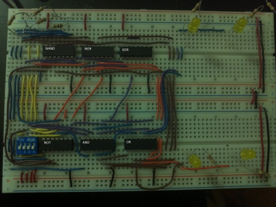
Using Boolean AND, NAND, OR, NOR, XOR, and NOT gates this project aimed to build a circuit that will convert the numbers 0-9 in binary to an analogue of braille. The system uses LEDs that will light up to represent a raised dot in the braille system and a dip switch to represent a 4-bit binary number as the input. This circuit is restricted to 4 dual input gates of each type, as well as 6 inverters.
Project 2
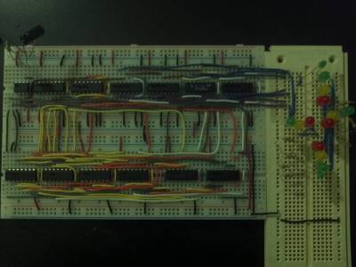
Traffic lights at a 4-way intersection depend on an important pattern of lights in each direction that optimize safety while keeping the stoplights from drastically inconveniencing the drivers or pedestrians. The purpose of this project was to establish a model stoplight that will light LEDs in a distinctive 48 second pattern to mimic red, green, yellow, and green turn lights. The materials used are limited to a single 4 bit counter, flip-flops, cmos logic gates, 555 timers and LEDs.
Final Project
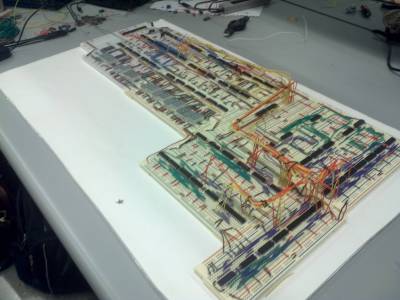
The final project was built and designed with my partner Aman Grewal. The circuit took an 8-bit binary number (0-255) via a dip-switch, and using a combination of logic gates, shift registers, 555 timers, comparators, multiplexers, demultiplexers, counters and 7-segment display drivers, output the prime factorization of that number in decimal.


