02/03/2012 Individual Sketches - Jae Sung Song
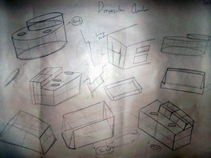
Sketch 1: General sketches of the preservation chamber
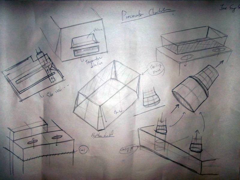
Sketch 2: General sketches of the preservation chamber and sub-functional parts
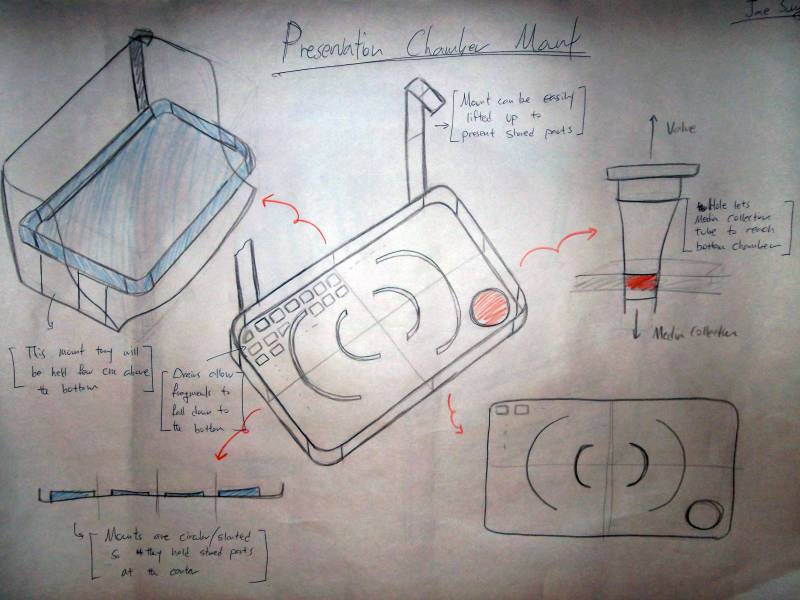
Sketch 3: Idea sketch of the allograft mount system. This system secures the body part and prevents it from floating around in solution. Furthermore, this system enables surgeons to easily locate stored parts because it can be easily removed from the chamber to expose stored parts.
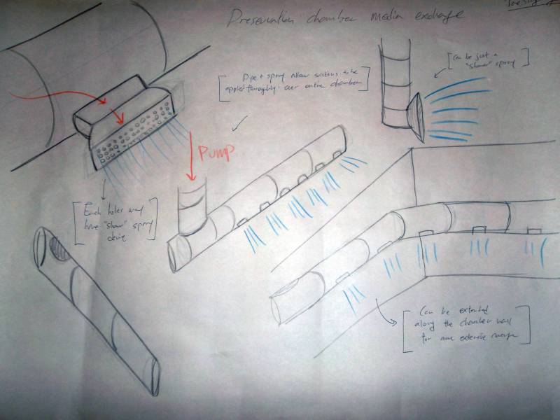
Sketch 4: This tube system sprays solution inside the chamber thoroughly. By spraying new solution over entire system thoroughly, liquids may be more effectively replenished.
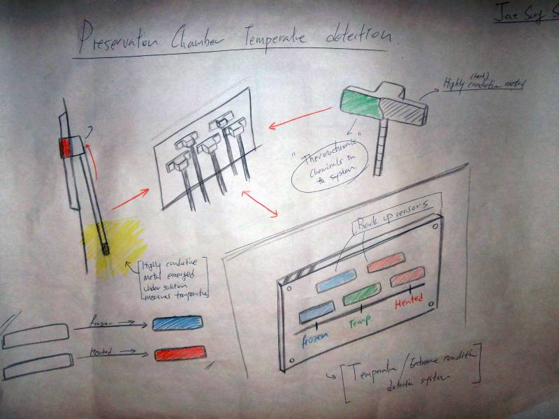
Sketch 5: This system measures temperature of solution inside the chamber. When heat-sensitive metal rods transfer heat, thermochromic chemicals inside the sensor react to the temperature and change their colors. This system may be used to indicate incidence of extreme conditions.
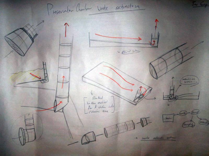
Sketch 6: The lower floor of the chamber is slightly slanted, providing natural current of solutions that make waste collection easier and more effective. The tube is attached at the lowest point.
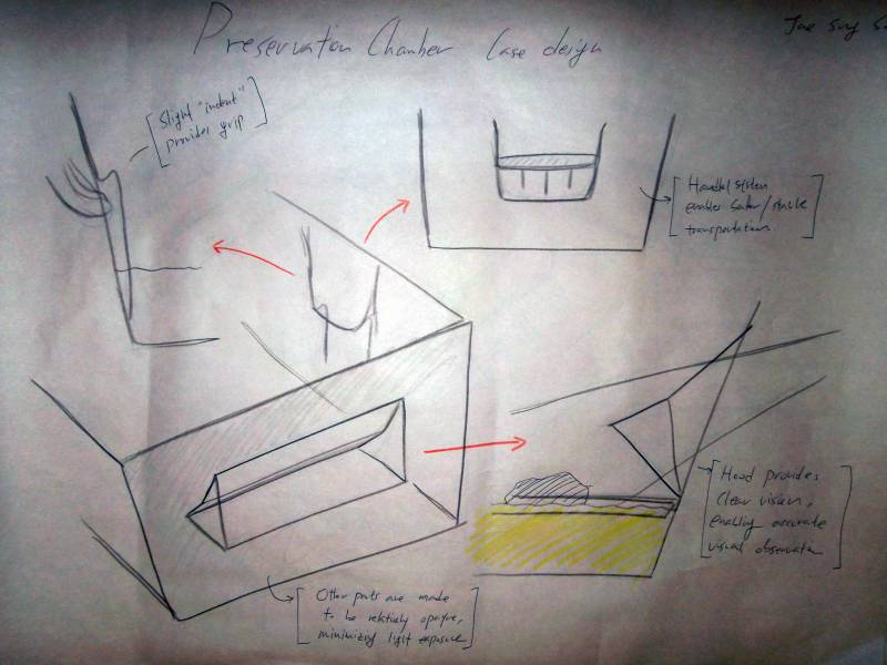
Sketch 7: The chamber may have small handles on its sides in order to make the process of transportation easier and safer.
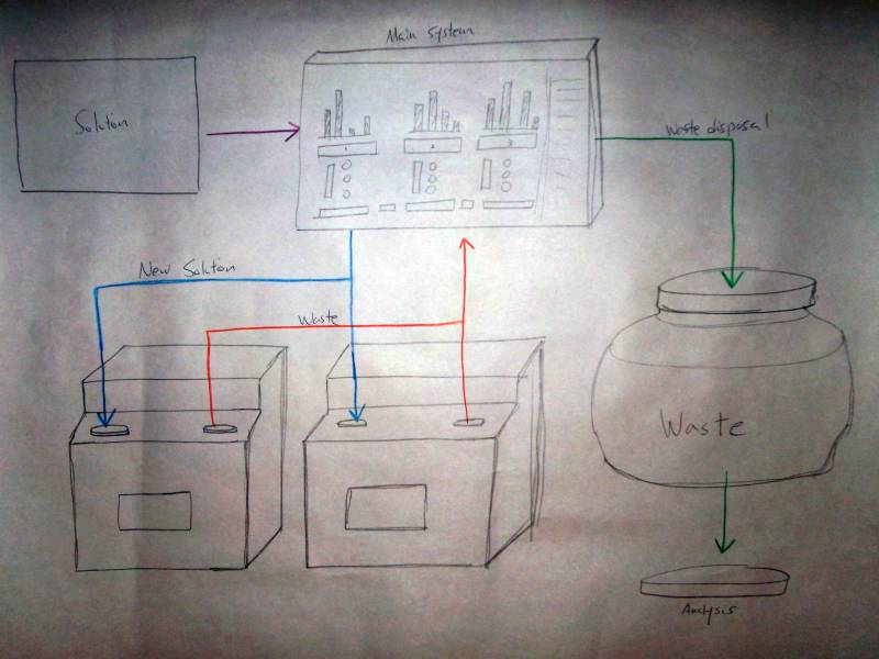
Sketch 8: Multiple chambers may be managed by comprehensive system with a main control monitor.
