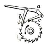
Description of Double Pawl Ratchet Construction
 Note: ‘A, ‘B, ‘C will refer to points where pawls A, B, C are secured
-All parts were laser-cut
-Parts were traced directly from picture above, modification of A was done around reference of locations ‘A, ‘B, and ‘C
-A and the Ratchet Axle were secured using a bolt with a through hole and then a threaded hole on the support wall
-B and C were sandwiched by 2 A levers, spacers to ensure ease of motion of B and C were only used on ‘A, about 1/64” clearance on each side of B and C was created
-B and C were secured via press fit of ‘B and ‘C on A using .06” diameter steel rod. The through holes of B and C were .0605” diameter and the holes for ‘B and ‘C on A were .058” diameters these dimensions were effective for creating an functioning press fit and allowing B and C to swing freely with little resistance
-The pawls were constructed out of ¼” acrylic, for this case the force of gravity was sufficient for total functionality of the double pawl ratchet
-Torsional (2D Helix Style) springs or standard tension compression springs can be used at ‘B and ‘C to ensure functionality at any angle
-It is recommended that a cardboard prototype is constructed first to make sure that parts function as intended
-One problem eliminated by prototype testing is that B is too long or the ratchet is placed to high, B will become wedged between its engaged tooth and the next one(the ratchet will not move)