This is only an example/test code that I used to see if the i/o expander would still work with the light sensors (which it did). If anyone needs to make up their own, they may remove all sub-functions and whatever is in the loop function to get it to work. All you have to do to go to a certain address of the i/o expander is to digitalWrite Apin through Epin to the values of A through E. (see the beginning of the reads sub-function).
For this i/o expander, we used 4 4051's–three were attached to the first three address lines of the first.
Here is the datasheet
*Look at the bottom of the page for an update to the convert subfunction.
//This is i/o expander has 18 possible outputs--possible 32 if convert is edited
//it's loop will only go through the lowest 6 addresses and will read the light sensor at each, one at a time


int reads(int led);//read led
int readsavg(int n, int led);//takes average of n readings for led
int convert(int i);

int anodePin=4;//all led's use this pin for their long leg

int Apin=14;//A0
int Bpin=15;//A1
int Cpin=16;//A2
int Dpin=17;//A3
int Epin=18;//A4
int cathodePin0=19;//A5

int A;
int B;
int C;
int D;
int E;

void setup(){
  _SFR_IO8(0x35) |= 4;
  _SFR_IO8(0x35) |= (1<<4);

  pinMode(anodePin, OUTPUT);  //set pins associated with led light sensors to outputs
  pinMode(Apin, OUTPUT);
  pinMode(Bpin, OUTPUT);
  pinMode(Cpin, OUTPUT);
  pinMode(Dpin, OUTPUT);
  pinMode(Epin, OUTPUT);
  pinMode(cathodePin0, OUTPUT);


  digitalWrite(anodePin, HIGH);
  digitalWrite(cathodePin0,LOW);

  digitalWrite(Apin,LOW);
  digitalWrite(Bpin,LOW);
  digitalWrite(Cpin,LOW);
  digitalWrite(Dpin,LOW);
  digitalWrite(Epin,LOW);

  Serial.begin(9600);
}
void loop(){
  int n=3;
  for(int j=0; j<6; j++){
    int i=readsavg(n,j);
    Serial.print("j is");
    Serial.println(j);
    Serial.print("i is");
    Serial.println(i);
    delay(1000);
  }
}
int reads(int led){
  led=led;
  int val = 0;
  int vcc=anodePin;
  convert(led);//get address of led
  //set multiplexer's to read that address
  digitalWrite(Apin, A);
  digitalWrite(Bpin, B);
  digitalWrite(Cpin, C);
  digitalWrite(Dpin, D);
  digitalWrite(Epin, E);


  digitalWrite(vcc,   HIGH);
  digitalWrite(cathodePin0, LOW);

 /* Serial.print(A);
  Serial.print(B);
  Serial.print(C);
  Serial.print(D);
  Serial.println(E);*/

  //already emitting light

  delay(50);

  //switch potentials -- charge LED to -5V
  digitalWrite(vcc,   LOW);
  digitalWrite(cathodePin0, HIGH);

  //measure time for potential to equalize (for cathode to be LOW)

  //switch pinmode
  pinMode(cathodePin0,  INPUT);

  //measure time it takes for cathodePin to go to zero
  //this value probably depends on the chip clock or something
  while((digitalRead(cathodePin0) != 0)&&(val<100)){
    delay(1);
    val++;
  }
  pinMode(cathodePin0,  OUTPUT);

  digitalWrite(vcc,   HIGH);
  digitalWrite(cathodePin0, LOW);
  //Serial.println(val, DEC);
  return val;
}

int readsavg(int n, int led){
  int val=0;
  for(int i=0; i<n; i++){
    val=val+reads(led);//read n times and sum
  }
  val=val/n;//divide by n for average
  return val;
}
int convert(int i){
  //converts a decimal number from 0 to 17, inclusively, to binary
  A=i/16;
  if(A==1){
    i=i-16;
    B=0;
    C=0;
    D=0;
    E=i;
  }
  if(A==0){
    B=i/8;
    if(B==1){
      i=i-8;
      C=i/4;
      if(C==1){
        i=i-4;
        D=i/2;
        if(D==1){
          i=i-2;
          E=i;
        }
        if(D==0){
          E=i;
        }
      }
      if(C==0){
        D=i/2;
        if(D==1){
          i=i-2;
          E=i;
        }
        if(D==0){
          E=i;
        }
      }
    }
    if(B==0){
      C=i/4;
      if(C==1){
        i=i-4;
        D=i/2;
        if(D==1){
          i=i-2;
          E=i;
        }
        if(D==0){
          E=i;
        }
      }
      if(C==0){
        D=i/2;
        if(D==1){
          i=i-2;
          E=i;
        }
        if(D==0){
          E=i;
        }
      }
    }
  }
}
**This is an update to the convert subfunction: I realized that the above chain of if statements was stupid and that there is a much better way to do it if you just put a bit more thought into it. So here it is:
void convert(int i){
  //This function handles numbers from 0 to 31
  A=i/16;
  i=i-(A*16);
  B=i/8;
  i=i-(B*8);
  C=i/4;
  i=i-(C*4);
  D=i/2;
  i=(D*2);
  E=i;
}

//so much nicer right
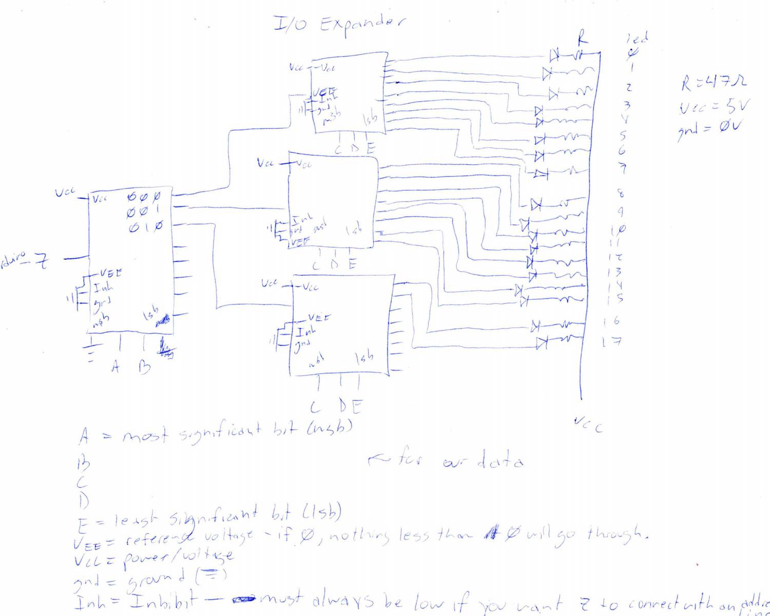
Here is the promised circuits diagram: