Open Source Electrospinning
Introduction
Electrospinning is a technique that is used to produce nano and micro scale fibers which have various applications in fields such as biomedical engineering. A syringe filled with a polymer solution is mounted on a syringe pump, which slowly pumps out droplets of solution. A strong electric field is set up in an enclosure using a high voltage power source. The electrostatic forces produced by this field propel the droplets from the tip of the syringe, spinning it into fibers which are then collected on a rotating mandrel or a collector plate. These fibers can then be collected for use in their specified application.
Principle of Operation
From Wikipedia (http://en.wikipedia.org/wiki/Electrospinning):
“When a sufficiently high voltage is applied to a liquid droplet, the body of the liquid becomes charged, and electrostatic repulsion counteracts the surface tension and droplet is stretched, at a critical point a stream of liquid erupts from the surface. This point of eruption is known as the Taylor cone. If the molecular cohesion of the liquid is sufficiently high, stream breakup does not occur (if it does, droplets are electrosprayed) and a charged liquid jet is formed.
As the jet dries in flight, the mode of current flow changes from ohmic to convective as the charge migrates to the surface of the fiber. The jet is then elongated by a whipping process caused by electrostatic repulsion initiated at small bends in the fiber, until it is finally deposited on the grounded collector. The elongation and thinning of the fiber resulting from this bending instability leads to the formation of uniform fibers with nanometer-scale diameters.”
Setup and Procedure
Summary
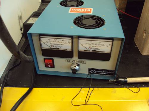
Our electrospinning apparatus consists of three main components: an enclosure, a syringe pump, and a high voltage power source. The enclosure was built to enhance safety as well as to minimize the effects of environmental factors, such as humidity, which can affect fiber formation. The enclosure is made entirely out plastic so it acts as an insulator. The high voltage power supply is used to produce an electric field with a potential difference between 10kV and 20kV. This electric field is produced by connecting the positive lead of the high voltage power supply to the needle of the syringe containing the polymer solution that is to be electrospun. The ground lead of the high voltage power supply is connected either to a metal collector plate or, in our case, a rotating mandrel. Fibers collected by a collector plate are randomly oriented on the plate, whereas fibers collected on a rotating mandrel show higher degrees of alignment at higher speeds (approximately 7000rpm). The syringe pump is used to pump out the polymer solution at the slow speeds (on the order of milliliters per hour) needed to successfully produce fine fibers. Once a droplet of solution forms on the tip of the syringe needle, the high voltage power supply is switched on and the electrospinning process begins.
For more complete information, check out the original senior project paper: electrospinning_snr_paper.doc
Also check out the photos and videos at the bottom of this page.
Setup
Layout
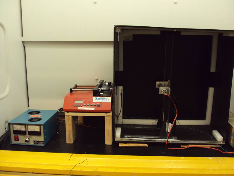
Our entire procedure is performed under a fume hood in order to allow proper ventilation for chemicals such as trifluoroethanol and because the fume hood is relatively isolated from the rest of the lab. The electrospinning enclosure is placed next to the syringe pump, and the syringe pump is oriented so the interface faces us. Your syringe pump should be on the side of the enclosure that the pump extrudes into, and the enclosure should have a clearance hole on this side for the syringe needle. The syringe pump should be placed on a stand so it is at approximately the center height of the enclosure. On the same side of the enclosure as the syringe pump, it is a good idea to have a hole to feed cables through to the high voltage power supply, which can be placed next to the syringe pump.
Wiring
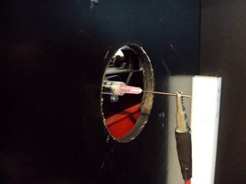
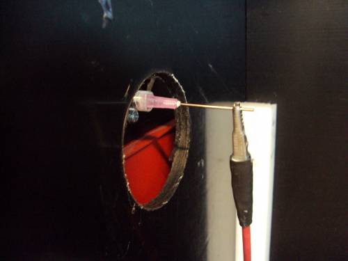
Both the high voltage power supply and syringe pump most likely have typical wall outlet connectors to plug in to. A cable rated for high voltage is fed from the positive lead of the power supply through the aforementioned cable hole and clipped near the tip of the needle you will be extruding your polymer solution from. If you construct a rotating mandrel, a wire from the ground lead of the high voltage power supply should be attached to a stationary part of the mandrel such as an angle bracket. If you are simply using a collector plate, connect this wire to the collector plate.
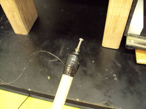
For safety, we use a “chicken stick,” which is simply a long rod with a grounded wire affixed to the end. The chicken stick is used to ground the electrospinner setup after each use. It is simply a wire attached to the end of a long rod. This wire should be of a length that does not make wielding the chicken stick difficult. One end of the wire is connected to the ground lead of the high voltage power supply, and the end on the rod is exposed. In our setup, a screw has been secured to the stick and the wire is secured to the screw; this setup allows us to be sure that an electrical contact is made when we ground the enclosure.
The motor driving the rotating mandrel simply needs some power source of its own such as a power supply. Adjust voltage and current settings so that your motor rotates at your desired speed.
Chemicals and Syringe
Electrospinning can be done with many different chemicals and liquids, so prepare whatever chemicals you use according to the quantity you need and according to whatever safety protocols are typical of your chemicals. When your solution is ready and you are ready to electrospin, load a small amount (such as a milliliter) into a syringe. The tip of the needle you use must be filed down so droplets of solution have a blunt surface to form on. If you use a viscous fluid, use a needle and syringe with a Luer-Lok connector. We have had good luck with BD Product #309628.
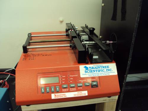
Once your syringe is loaded, mount it on your syringe pump according to the manufacturer’s instructions. We programmed our syringe pump to pump at 5mL/hr. When the syringe is mounted, attach the cable coming from the positive lead of the high voltage power supply to the needle tip. If all the electrical connections have been made properly, you are ready to begin electrospinning.
Procedure
At this point, you should have all the electrical connections made properly, a syringe loaded with your solution, and a syringe pump programmed to extrude at your desired rate. When everything is ready, activate the syringe pump. Wait for a droplet of solution to form on the tip of the needle and then activate the high voltage power supply. It is a good idea to make sure the high voltage power supply is pre-set to the desired voltage. If you are using a rotating mandrel, turn it on at this time as well.
A very fine, almost invisible stream of fibers should begin propelling from the needle to your collector. If fibers collect on an enclosure wall instead, it means one of the electrical connections is too close to part of the enclosure. Run the electrospinner for as long as desired.
Once you are done electrospinning, the first thing to do is turn off the high voltage power supply. Before doing anything else, the needle and enclosure need to be grounded. With one hand behind your back for electrical safety, touch the end of the chicken stick to the needle and to a wall of the enclosure. After everything is grounded, it is safe to turn off the syringe pump and rotating mandrel and collect your fibers.
Bill of Materials
The two most expensive components of the apparatus are the Syringe Pump and the High Voltage Power Supply. If you have any of these devices on hand, we obviously recommend you use those instead of specifically ordering the ones we used in our setup. The materials listed for the enclosure construction are there primarily as a guideline in the event that you want to build an enclosure very similar to ours. However, we strongly encourage you to design your own to suit your needs. It simply needs to be electrically insulating, shield the electrospinning process from ambient factors such as humidity, and be large enough to perform the procedure in.
Download Bill of Materials as Excel spreadsheet: electrospinner_bom_2.xls
Assembly and Resources
Enclosure and Collector Plate Stand
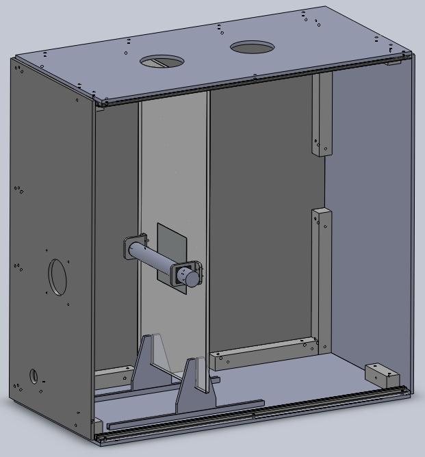
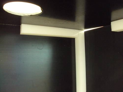
The enclosure currently used in our setup is a hand-me-down from the group that began the electrospinning project. It consists mainly of three 24” X 24” HDPE sheets cut to various sizes which serve as the walls of the enclosure. Teflon bars with 1” square cross-sections have had holes drilled and tapped into them and are used to support the enclosure. The enclosure walls are secured to the Teflon bars with #10-32 Nylon plastic screws. A 24” X 24” polycarbonate sheet is used as a door, which can slide in u-channels on the floor and ceiling of the enclosure. Two holes were cut in the left wall: one to serve as clearance for the syringe needle and one to feed the cables from the high voltage power supply through. The syringe needle clearance hole is large enough to prevent electrical arcing from the needle to the enclosure wall when the high voltage power supply is turned up to the required voltage.
Inside the enclosure, there was initially a polycarbonate stand with a thin aluminum plate that served as the collector plate. The stand was supported by Teflon blocks at the bottom and top that were secured to it with Nylon plastic screws. Velcro was attached to the Teflon blocks so they could be adjustably secured to the floor and ceiling of the enclosure.
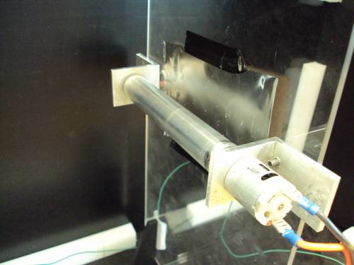
We have altered the original setup for our current purposes. We designed a new stand that has a rotating mandrel mounted to it. This stand is supported by two ¼” laser-cut pieces of ABS plastic that fit into u-channels at the floor of the enclosure. The stand fits securely into slots in each of the ABS plates. This setup allows the stand to be slid forward and back while still supporting it stably when the mandrel is rotating. We have also neglected the use of the polycarbonate door in this setup since the electrospinning procedure is performed in a fume hood. Furthermore, the enclosure itself is quite overdesigned. We encourage anyone creating their own setup from scratch to design their enclosure to be inexpensive and suit their needs, assuming an enclosure is desired at all. It also should be built out of insulating materials such as plastic for safety and to ensure that the high voltage electric field only exists between the syringe needle and the mandrel or collector plate.
Rotating Mandrel
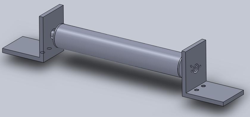
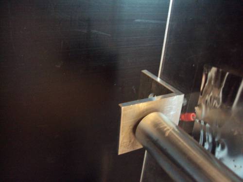
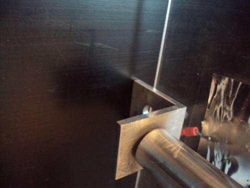
The Mandrel Assembly consists of an aluminum tube, two aluminum plugs, and two aluminum square brackets. The tube was machined to have a uniform inner and outer diameter throughout its length so it is properly balanced while rotating. The plugs were machined from a section of aluminum rod. One plug has a through-hole that the rod from our motor is inserted into, and it has small threaded holes on the rod for set screws to secure the motor rod. Both plugs are press-fit into the mandrel tube, so they have to be carefully machined so that they are also uniform and properly mate with the mandrel tube. The specific inner value of the inner diameter of the tube and plugs should not matter too much; the key is that the plugs can be successfully press-fit into the tube. One of the aluminum brackets has holes for the motor tube to fit through and holes for screws so the motor can be attached. The other bracket has a hole for a bearing to be press fit into. The plug that is not secured to the motor is fit into the bearing. The brackets also have threaded holes for screws so the mandrel assembly can be mounted on the collector stand.
Solidworks models and drawings, drawings as PDFs: mandrel.zip
Safety
There are three sources of danger in this procedure: The high voltage power supply, the chemicals used, and the rotating mandrel.
- During the procedure, the high voltage power supply will produce a potential difference of 20kV. The use of such a high voltage carries the risk of electric shocks due to either direct contact with exposed circuitry or possible capacitive effects within the enclosure. In addition, the risk of static electricity must be minimized due to the flammability of the trifluoroethanol solvent. To minimize such risks, the following protocol must be adhered to during every electrospinning session:
- The output of the high-voltage power supply will be shorted to ground when the supply is not in use to ensure that no charge remains at the output of the supply. This must be done immediately following shutdown of the power supply and before any adjustments are made to the test setup. Only one hand may be used to make the appropriate connection between the supply output and the ground, the other hand held behind your back, in order to minimize the chance that an accidental shock will result in electric current flowing across your chest. This connection will be made according to the following procedure, using a “chicken stick”1). The wire from the chicken stick will be connected to the high voltage power supply’s ground return at all times, as the ground return connection is on the back of the high voltage power supply, and therefore is difficult to access while the setup is in place.
- To ground the power supply, the procedure is as follows:
- Switch the power supply off.
- With one hand behind your back at all times, use the chicken stick to discharge the output of the high voltage power supply by touching the end of the wire to the syringe needle.
- Also touch the end of the chicken stick to one of the walls of the enclosure, as static charge tends to build up on the enclosure walls as well.
- An alligator clip test lead may now be used to temporarily connect the syringe needle to the power supply ground return.
- When turning on the power supply, the procedure is as follows:
- Check that the end of the wire from the chicken stick is connected to the ground return of the high voltage power supply. If that is the case, remove the connection between the output and the ground return. Otherwise, first connect the chicken stick, then proceed to disconnect the output from the ground return.
- Make sure the alligator clips coming from the positive and negative electrodes of the power supply are in their proper places attached to the syringe needle and collector plate, respectively.
- When you are ready to begin electrospinning, activate the syringe pump. The power supply is to be activated once a bead of polymer solution forms at the tip of the needle.
- In our setup, we used the chemicals polycaprolactone (PCL) and trifluoroethanol (TFE).
- The entire electrospinning procedure is always performed under a fume hood to allow chemical vapors to vent.
- PCL carries very little risk and is biodegradable.
- The main risk associated with TFE is its flammability. It must be stored in an appropriate cabinet or storage room designed for flammable materials, and must be kept away from possible sources of ignition.
- Gloves should obviously be worn when preparing the PCL solution.
- In case of spills, a sorbent such as kitty litter may be used to absorb the TFE and then be disposed of in an appropriate waste disposal.
- The rotating mandrel will be rotating at high speeds, so it must be properly secured to prevent it from coming loose and causing injury. The windows of our fume hood have been coated with an expensive impact-proof film, although it is unlikely that everyone replicating this procedure has the luxury of using such a material, so common sense should be enough to prevent any harm.
Media
Photos
Video
All video links redirect to YouTube.
